ENMET AM-5150 User Manual
Page 18
AM-5150
ENMET Corporation
16
5.3 Sensor Replacement
The MOS sensor is durable, it can be purged of contaminants by operating in PURGE for a sufficient length of time and at
regular intervals.
Gross contamination usually occurs during unavoidable misuse. Close exposure to an open gas flame, submersion of the sensor
in a liquid, or continuous exposure to heavy concentrations of industrial vapors will grossly contaminate a sensor. A grossly
contaminated sensor causes a continuous alarm.
If a sensor fails to calibrate, replace it.
P
ROCEDURE
:
W
ARNING
:
Power must be removed from the
AM-5150
before this or any internal procedure. Failure to do so may cause
damage to equipment, bodily injury or death.
1.
Obtain a new sensor assembly. Make sure the sensor type is identical to your original sensor
Sensor marking is on side of sensor see Figure 9
(Example: 813-4 the first 3 digits are sensor ID the 4 digit indicates a 4-wire sensor).
2.
Disconnect the instrument for power.
3.
Disconnect the orange, brown, blue and yellow sensor wires.
4.
Unscrew the assembly from the sensor enclosure.
5.
Remove the bad sensor.
6.
Replace with the new sensor and reconnect the wires (See Section 3.2.1).
N
OTE
: The user must perform the four color-coded wiring attachments when replacing the sensor. If the yellow signal wire
is not connected to the terminal block, use supplied wire nut.
7.
Reconnect the instrument to power and verify sensor heater voltage. (See Section 3.2.1)
8.
Recalibrate the instrument (See Section 5.3.1).
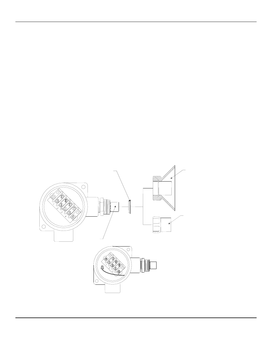
Figure 9: AM-5150 Sensor Replacement
After the new sensor assembly has been installed, it is suggested to allow the sensor to stabilize for at least 3 – 4 hours,
preferably over night.
Sensor
Spacer Ring
*Replace facing direction as shown
Optional Splash Shield
Standard Sensor Shield
View of 3-wire Terminal
View of 4-wire Terminal