Elenco Digital Multimeter User Manual
Page 15
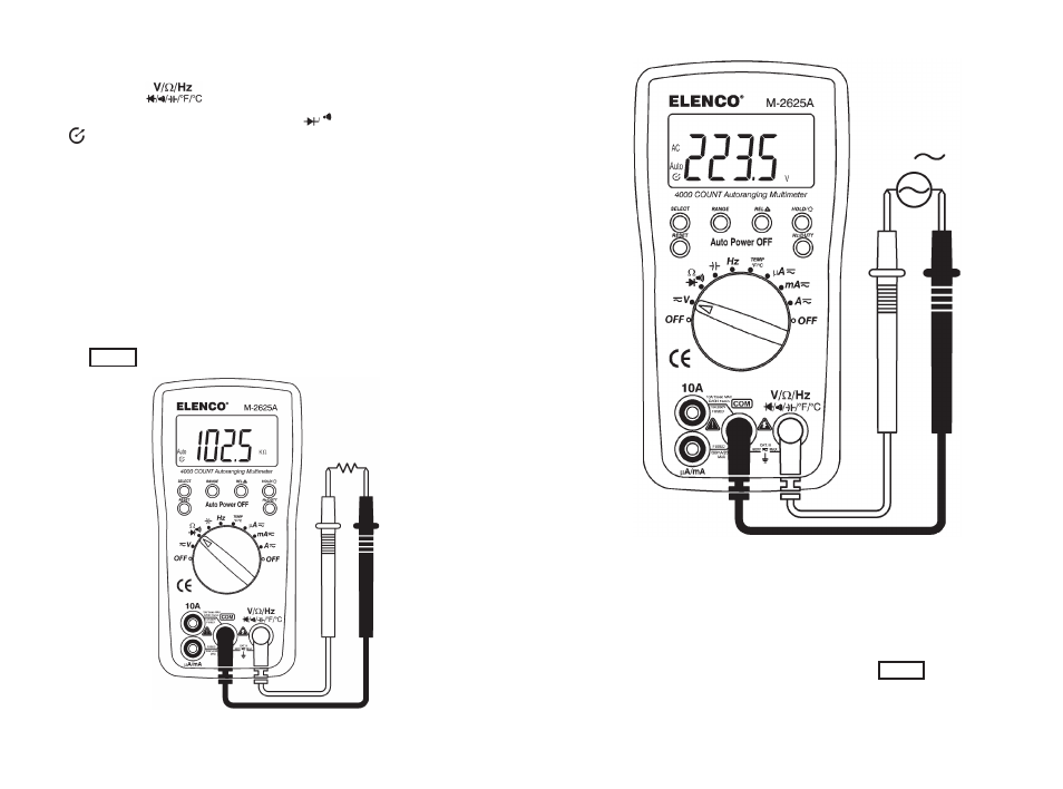
1. To measure resistance, turn on the meter, then set up the meter
as shown in Figure 10.
2. Insert the black test lead into the
COM
terminal and the red test
lead into the terminal.
3. Set the Function Rotary Switch to the
Ω
position (then, “AUTO”,
“ ”, “OL”, and “M
Ω
” symbols are indicated on the display).
4. Connect the test leads to both ends of the resistance under test,
then the measured value is shown on the display.
Keep the following in mind when measuring resistance:
• Because the meter’s test current flows through all possible paths
between the probe tips, the measured value of a resistor in a
circuit is often different from the resistor’s rated value.
• The test leads can add 0.1
Ω
to 0.2
Ω
of error to resistance
measurements. To test the leads, touch the probe tips together
and read the resistance of the leads. If necessary, you can press
the
REL
Δ
button to automatically subtract its value.
Figure 10. Resistance Measurement
-22-
Figure 7. AC Voltage Measurement
Note:
When taking a measurement of less than 20mV at the 400mV
AC range, the measurement value cannot be indicated correctly.
Even if shorted, the input line at the 4V AC range, 1 ~ 3 digits may
remain indicated. In that case, by pressing the
REL
Δ
button, “0” will
be indicated.
-15-
V
Ω