Caution – Elenco Digital Multimeter User Manual
Page 14
Measuring AC Voltage
1. Turn on the meter, then set up the meter to measure AC volts as
shown in Figure 7.
2. Insert the black test lead into the
COM
terminal and the red test
lead into the terminal.
3. Set the Function Rotary Switch to the
~V
position and press
SELECT
to select the AC voltage measuring mode (then,
“AUTO”, “AC” and “V” symbols are indicated on the display).
4. Connect the test leads to the circuit under test, then the
measured value is indicated on the display.
5. When measuring voltage less than 400mV, press the
RANGE
button to switch to manual range mode and select the AC 400mV
range. Doing so will provide a better resolution for your
measurement.
6. You can press the
Hz/DUTY
button to read the signal frequency
or duty cycle under measurement from the display.
-14-
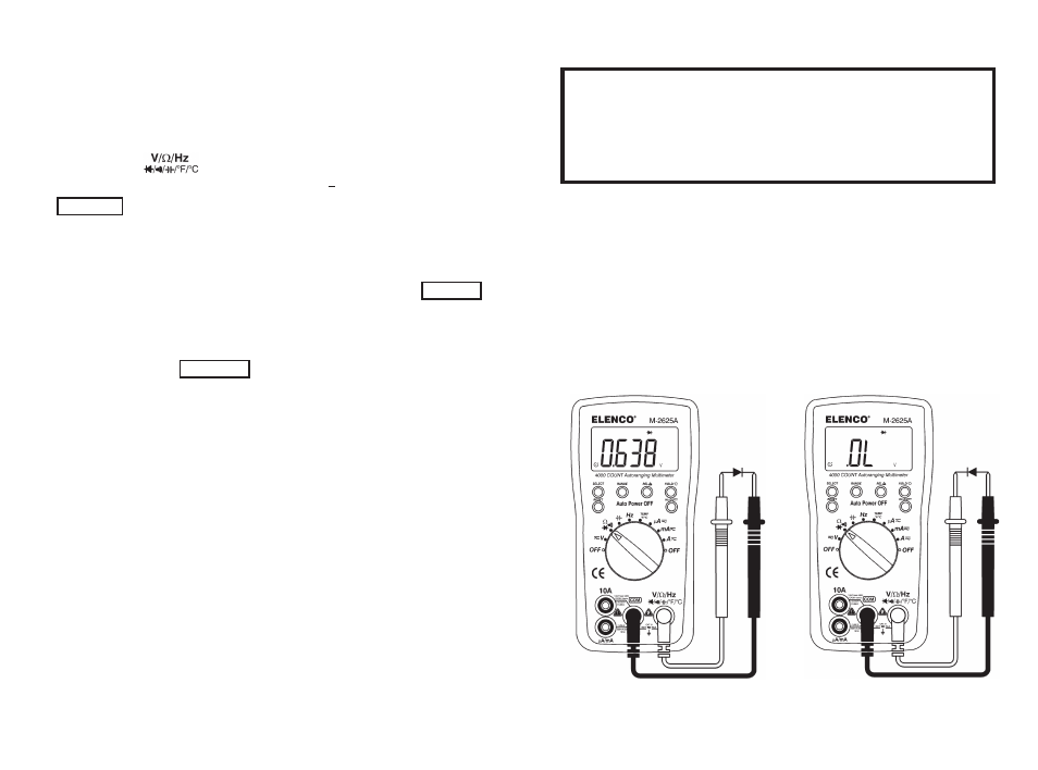
Testing Diodes
Caution
To avoid possible damage to the meter or to the equipment
under test, disconnect the circuit power and discharge all
high-voltage capacitors before testing diodes.
Use the diode test to check diodes, transistors, silicon controlled
rectifiers (SCRs), and other semiconductor devices. The test sends
a current through a semiconductor junction, then measures the
junction’s voltage drop. A typical junction drops 0.5V to 0.8V.
To test a diode out of a circuit, set up the meter as shown in
Figure 11. In a circuit, a similar diode should still indicate a
forward-bias reading of 0.5V to 0.8V; however, the reverse-bias
reading can vary depending on the resistance of other pathways
between the probe tips.
Figure 11. Diode Test
-23-
Forward Bias
+
–
Reverse Bias
–
+