Project 4 heavy load, Project 3 triple voltage divider, Project 5 heavy flow – Elenco Basic Electricity User Manual
Page 2
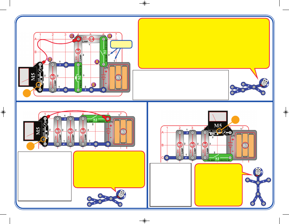
Project 4
Heavy Load
Modify the preceding circuit
to match this one. Set the
meter (M5) to the 1A setting
and turn on the switch (S1).
The meter measures the
current. Try removing one
or two lamps and see how
the current changes. Also
try this circuit with both new
strong batteries and with old
weak ones.
This circuit is pictured on the front of the box, use that picture to help
in building it. Set the meter (M5) to the 5V setting. Turn on the slide
switch (S1) and use the meter to measure the voltage at points A, B,
C, D, & E in the circuit by connecting the end of the red jumper wire
to each of those points (the drawing shows it connected to point C).
Next, repeat the voltage measurements at points A, B, C, D, & E
while pushing the press switch (S2).
Project 3
Triple Voltage Divider
5V
Placement
Level Numbers
The circuit has three lamps connected in series, or two when S2 is pressed (S2 bypasses the last one).
A. Point A is the “+” battery terminal, so the meter is always measuring the battery voltage.
B. When S1 is on, point B is connected to the batteries, so the voltage will be the same as point A. When
S1 is off, the voltage is zero.
C. Point C measures the voltage after one lamp and across the other two, so should be about 2/3 of the
battery voltage. When S2 is pressed, the last lamp is bypassed, so point C is measuring across one of
the two remaining lamps, so should be approximately 1/2 of the battery voltage.
D. Point D measures the voltage after two lamps and across the last one, so should be about 1/3 of the
battery voltage. When S2 is pressed, the last lamp is bypassed, so point D is zero volts just like point E.
E. Point E is the “—” battery terminal, and will always be zero.
Kirchhoff’s Voltage Law, an important rule for analyzing circuits, says the total voltage driving a circuit must
equal the voltage drops within it. So the voltage drops across all of the lamps should equal the battery
voltage. (Your measurements may be a little different, because M5 is a simple meter with low accuracy.)
Set the meter (M5) to the 5V setting,
and initially keep the switch (S1) off.
The meter measures the battery
voltage with the lamps (L4) off.
Now turn the switch on to light the
lamps, and see if the battery voltage
changes. Next, remove one or two of
the lamps and compare the voltage.
Try this project with both new strong
batteries and with old weak ones.
Compare how the voltage changes
when you turn the switch on.
Project 5
Heavy Flow
1A
In this circuit, electricity flows out
of the batteries, through the meter,
then divides among the 3 lamps,
then all flows back to the batteries
through the switch.
The 3 lamps are connected in
parallel, because the current flow
divides among them. If one of the
lamps burns out, the others will
still work because has its own path
for electricity to flow along.
Batteries produce electricity using a chemical reaction,
and only a limited amount of the chemicals can react
together at once. Also, the chemical reaction slows as the
batteries get weaker. When a circuit wants more
electricity than the batteries can supply, the voltage
(electrical pressure) drops.
In this circuit, lighting all three lamps takes a lot of
electricity, so the voltage drops a little when the switch is
turned on. The drop in voltage is much greater for weak
old batteries than for strong new ones.
5V
SCP-10_021714.qxp_SCP-10_Instructions 3/7/14 2:35 PM Page 2