Schematic diagram, Troubleshooting – Elenco LED Robot Blinker User Manual
Page 7
-6-
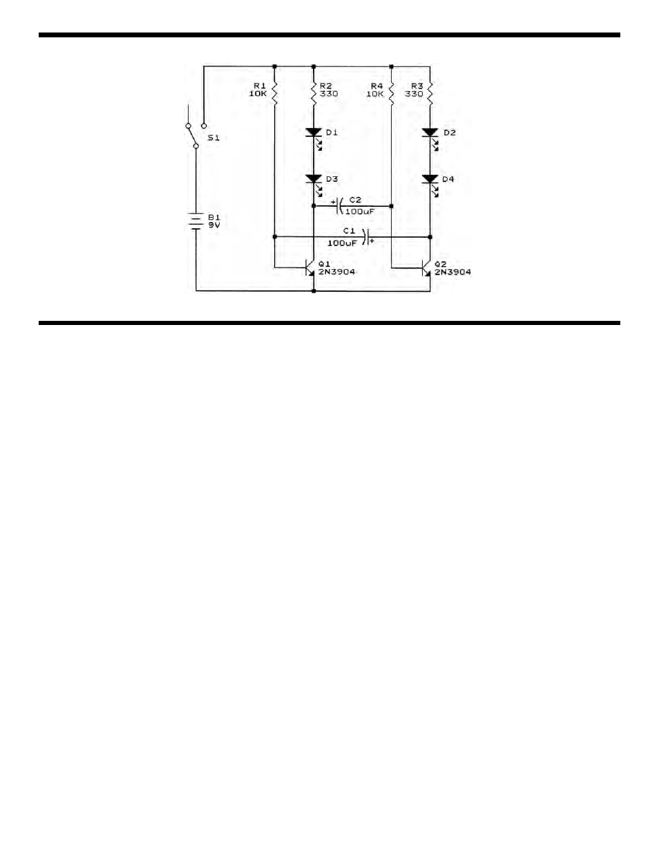
SCHEMATIC DIAGRAM
Consult your instructor or contact ELENCO
®
if you
have any problems. DO NOT contact your place of
purchase as they will not be able to help you.
One of the most frequently occurring problems is
poor solder connections.
a) Tug slightly on all parts to make sure that
they are indeed soldered.
b) All solder connections should be shiny.
Resolder any that are not.
c) Solder should flow into a smooth puddle
rather than a round ball. Resolder any
connection that has formed into a ball.
d) Have any solder bridges formed? A solder
bridge may occur if you accidentally touch an
adjacent foil by using too much solder or by
dragging the soldering iron across adjacent
foils. Break the bridge with your soldering
iron.
The LED’s will not light
1. Use a fresh 9 volt battery.
2. Check to see that the battery snap is correctly
mounted to the PC board.
3. Check to see that the LED’s are mounted
correctly. Short the cathode of LED D1 to the
negative (–) battery lead. The LED should light. If
not, it is then in backwards or defective. Do the
same with LED D3. Both LED’s should light up.
Repeat with LED’s D2 and D4.
4. If the LED’s still don’t light, check the battery snap
wiring. The wires must be as shown in the
assembly diagram. Be sure that resistors R2 and
R3 are the correct values (330
Ω
).
5. Check transistors Q1 and Q2. Be sure that they
are in correctly. The flat side should be in the
direction as shown in the pictorial diagram.
6. Check the switch S1. Short the lugs of S1 with the
two wires. If the LED’s light, the switch is not
good.
The LED’s will not blink
1. If only one pair of LED’s light, then check the
transistor whose LED’s are not lit. Replace if
necessary.
2. If all four LED’s are lit, then check to see if
capacitors C1 & C2 and resistors R1 & R4 have
been installed correctly.
TROUBLESHOOTING