Assemble components to the pc board – Elenco LED Robot Blinker User Manual
Page 6
-5-
Figure B
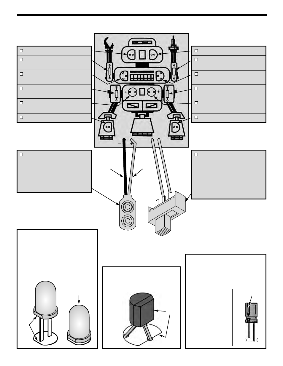
Mount the transistor on the position shown.
Make sure that the flat side of the transistor
agrees with the flat side of the marking on the
PC board.
ASSEMBLE COMPONENTS TO THE PC BOARD
D2 - LED (see Figure A)
R3 - 330
Ω
5% 1/4W Resistor
(orange-orange-brown-gold)
Q1 - 2N3904 Transistor
(see Figure B)
R1 - 10k
Ω
5% 1/4W Resistor
(brown-black-orange-gold)
C2 - 100
μ
F Electrolytic Cap.
(see Figure C)
D3 - LED (see Figure A)
D1 - LED (see Figure A)
R2 - 330
Ω
5% 1/4W Resistor
(orange-orange-brown-gold)
Q2 - 2N3904 Transistor
(see Figure B)
R4 - 10k
Ω
5% 1/4W Resistor
(brown-black-orange-gold)
C1 - 100
μ
F Electrolytic Cap.
(see Figure C)
D4 - LED (see Figure A)
Flat
S1 - Slide Switch - Cut two 4”
wires and strip 1/2” of insulation
off of both ends of the wires.
Solder a wire to the middle lug
and the other wire to one of the
other lugs. Insert the other ends
into the PC board. Solder and cut
off the excess leads.
B1 - Battery Snap - Install the
red wire into the positive (+) hole
and the black wire into the
negative (–) hole as shown. Bend
the leads to hold the battery snap
in place. Solder and cut off the
excess leads.
Red
Black
Wear safety goggles when
assembling.
'
Figure C
Electrolytic capacitors have polarity.
Be sure to mount them with the
negative (–) lead (marked on side) in
the correct hole.
Warning: If the
capacitor is
connected with
incorrect polarity,
it may heat up
and either leak
or cause the
capacitor to
explode.
Polarity
marking
(–)
(+)
Figure A
Mount the LED onto the PC board
with the flat side of the LED in the
same direction as marked on the PC
board. Be sure to mount the LED
flush with the PC board as shown
below.
Solder and cut off the excess leads.
Flat
Mount flush
to PC board