Start-up stage, Continuous cycle stage, Introduction – Elenco LED Robot Blinker User Manual
Page 4: Component operation
-3-
START-UP STAGE
Looking at the schematic diagram (on page 6) shows that the circuit is essentially
symmetrical. There are two transistors, capacitors, LED’s and resistors. These
components are wired exactly the same. If all of the components were exactly
the same, then this circuit could not work. In reality, the components’ tolerances
are different. When the power is turned ON, one branch will conduct faster than
the other. This causes the slower branch to turn OFF. Let’s assume transistor
Q1 conducts first and therefore LED’s D1 and D3 turn ON as shown in Figure 2.
The collector voltage of Q1 immediately goes slightly above the emitter voltage,
therefore charging capacitor C2 through resistor R4. The time it takes to charge
capacitor C2 determines the frequency or “blink rate” of the Robot Blinker. In our
case, it takes about 1/4 of a second. As long as C2 is charging, the current
through resistor R4 will produce a negative voltage at the base of transistor Q2,
keeping this transistor turned OFF.
CONTINUOUS CYCLE STAGE
We’ve learned that as long as C2 is charging, the current through R4 will keep
transistor Q2 OFF. When C2 is near full charge, the current through R4 will
reduce, causing the voltage at the base of Q2 to rise to .7V above its emitter.
This begins to turn transistor Q2 ON. At this moment, the collector voltage of Q2
drops and capacitor C1 begins to charge. The current through R1 produces a
negative voltage at the base of Q1, causing a rapid shutdown of Q1 and a rapid
turn ON of Q2.
The process now repeats itself with Q2 conducting until capacitor C1 nears full charge and begins to turn
transistor Q1 ON. Effectively the two transistors will alternately turn ON and OFF every 1/2 second. The voltage
on the collector will form a square wave as shown in Figure 3. Whenever the voltage goes negative, a current
will flow in the two associated LED’s and light will be emitted.
B1
R2
Q1
S1
R1 D1
D3
C2
Figure 2
Figure 3
Q1
Q2
0
0
+
+
1/2
sec
R4
INTRODUCTION
The Robot Blinker alternately flashes a pair of LED’s (light emitting diode) on at about two blinks per second. The
circuit is basically an astable multivibrator or free-running oscillator. In analyzing how it works, we will look at the
start-up stage and then at the continuous cycle stage where the LED’s flash at a continuous two cycles per
second.
COMPONENT OPERATION
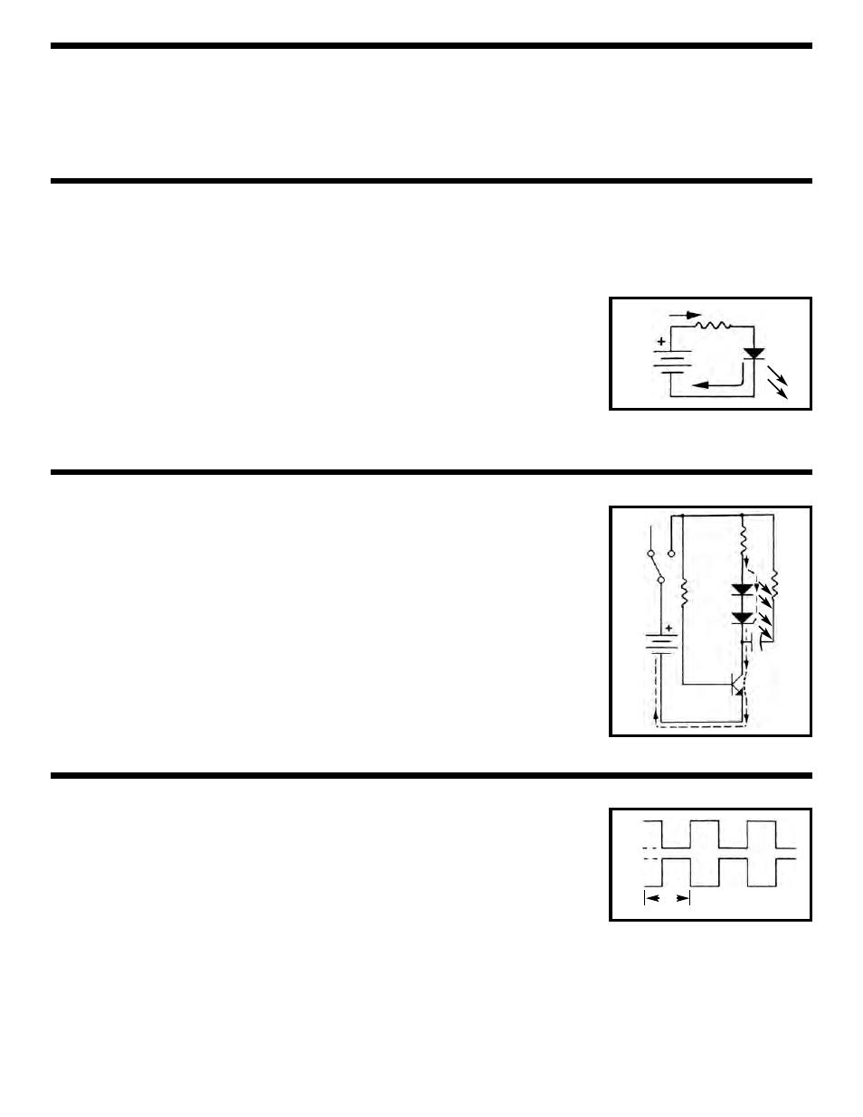
Let’s first review the operation of critical components. A light emitting diode (LED) is a device that emits light
whenever a current passes through it. The more the current, the brighter the light. See Figure 1, resistor R2 is
placed in series with the LED to limit the current to the desired amount.
An NPN transistor is a device that amplifies and controls the current. It consists
of three elements: Base, Emitter, and Collector. The emitter is connected to a
negative voltage and the collector to a positive voltage. The base controls the
collector-emitter, the collector will conduct current to the emitter when the
voltage across the base-emitter junction is .7V. This current is many times the
base emitter current and therefore the transistor is said to be amplifying the
current. A capacitor is a device that stores current and a resistor is a device that
limits current.
Figure 1
LED
9V
R2