Elenco AM Radio Kit User Manual
Page 16
Measure the maximum voltage peak to peak when clipping
first occurs and record that value here:
Vclp = _______ Vpp.
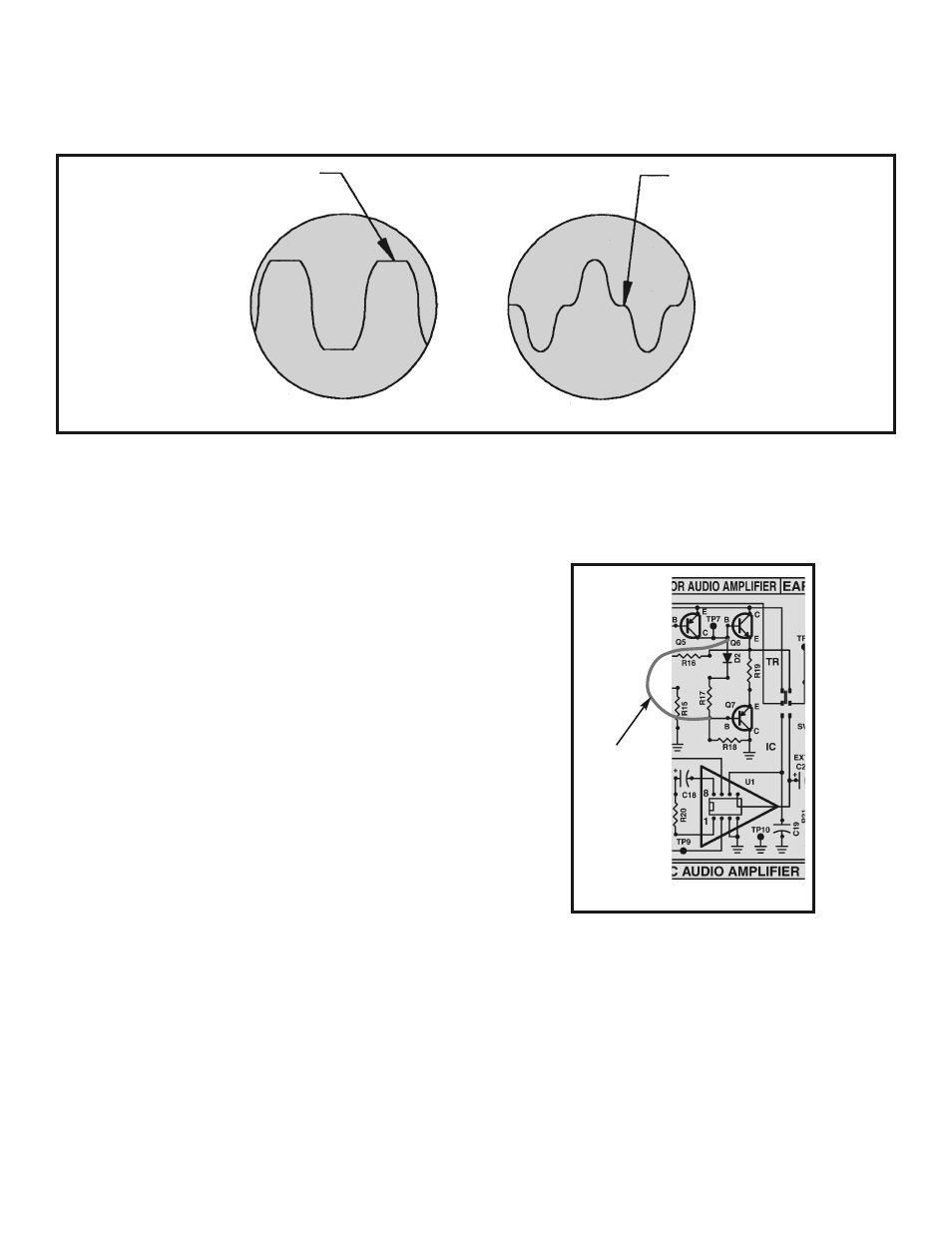
Using a wire short out resistor R17 and diode D2 as shown
in Figure 10.
The waveform on your oscilloscope should resemble
Figure 9B. The “flat spots” near the center of each
sinewave demonstrate what is called crossover
distortion. This distortion should disappear when you
remove the shorting lead. Turn the power OFF
The maximum power output before distortion due to
“clipping” can be calculated using the voltage Vclp
obtained in step 4 as follows:
Vpeak (Vp) = Vclp/2
Vroot mean squared (Vrms) = Vp x .7
Max power out = (Vrms)
2
/8 ohms = (Vclp x .35)
2
/8
Maximum power output should be greater than 200
milliwatts.
MAXIMUM POWER OUTPUT
Connect the generator and oscilloscope as shown in
Figure 8. Set the generator at a frequency of 1kHz, turn
the power ON and adjust the generator output until the
peaks of the sinewave at TP8 are clipped as shown in
Figure 9A.
DISTORTION
-15-
Clipped
Crossover distortion
Figure 9
A
B
Figure 10
Wire lead
or clip lead
By measuring the DC power taken from the battery at
the maximum power output level, the efficiency to the
Audio Amplifier can be calculated. Power from the
battery is equal to the current taken from the battery
times the voltage of the battery during maximum power
output. It is best to use a power supply to prevent battery
voltage from changing during this measurement.
Efficiency can then be calculated as follows:
Eff =
EFFICIENCY
Max audio power
Battery power
/