Elenco AM Radio Kit User Manual
Page 11
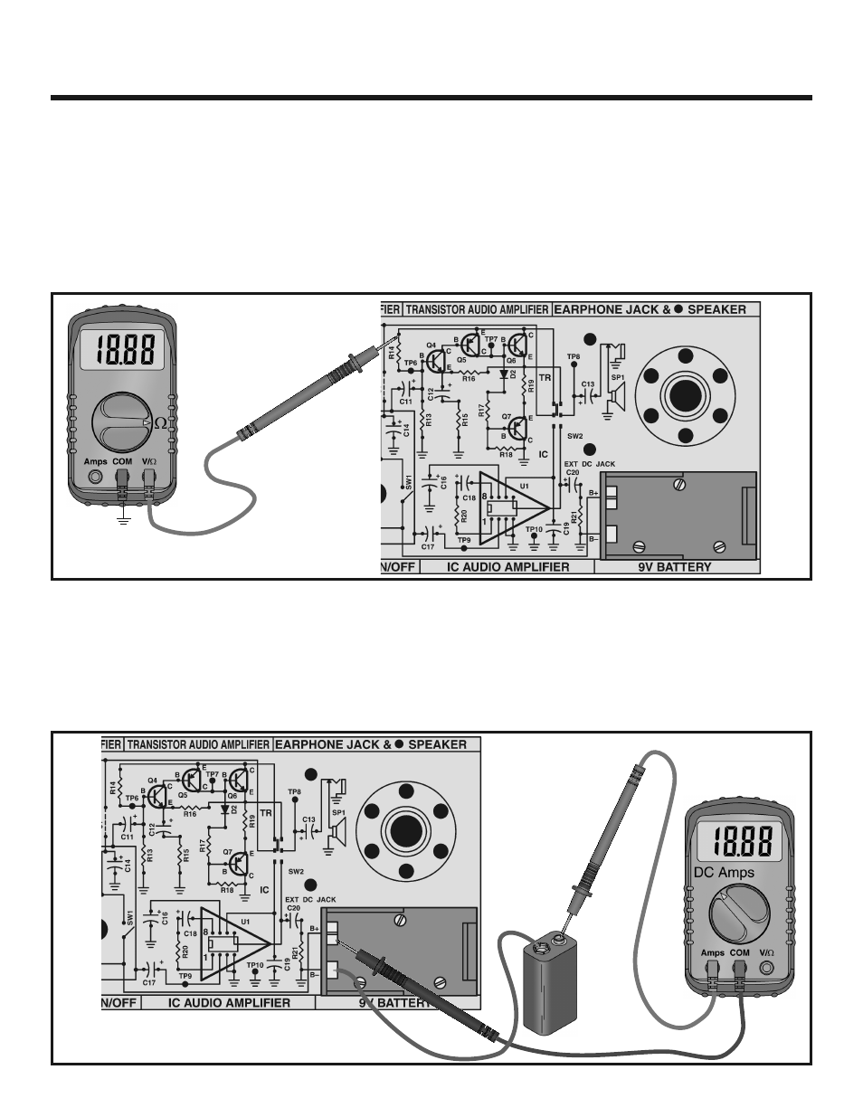
STATIC MEASUREMENTS - TRANSISTOR AUDIO AMPLIFIER
(SW2 on the top [TR] position)
RESISTANCE TEST
-10-
+
You have completed wiring the Transistor Audio Amplifier. We shall proceed in testing this circuit. You will need a Volt-
Ohm-Milliammeter, preferably a digital type.
Adjust the Volt-Ohm-Milliammeter (VOM) to the highest
resistance scale available. Connect the VOM to the circuit
as shown in Figure 3. Do not connect the battery.
The VOM should indicate a low resistance first and then
as C14 charges, resistance should rise to approximately
100k
Ω. If you get a lower reading, reverse multimeter
leads. If you get a reading lower than 20k
Ω, check the
circuit for shorts or parts inserted incorrectly. Check C14
to see if it’s leaky or inserted backwards. If you get a
reading higher than 150k
Ω, check for open copper or
bad solder connections on resistors R13 and R14.
Figure 3
Figure 4
Set your VOM to read the highest possible DC current.
Connect the meter to the circuit as shown in Figure 4.
Make sure that the On/Off switch (SW1) is in the OFF
position.
While watching your VOM, flip switch SW1 to the ON
position. The VOM should indicate a very low current.
Adjust your meter for a more accurate reading if necessary.
If the current is greater than 25 milliamps, immediately turn
the power off. The current should be between 5 and 15
milliamps. If you circuit fails this test, check that all parts
have been installed correctly and check for shorts or poor
solder connections. Turn OFF SW1.
POWER UP TEST
GND
TP10
–