Warning – EarthQuake 26750 User Manual
Page 12
Check for parts online at
www.getearthquake.com or call 800-345-6007 M-F 8-5
12
Operator's Manual
VECTOR™ Compact Tiller
OPERATION
CONTROLS
Drive Safety Control Lever
Engage tines into forward, releasing returns machine to
neutral. Pulling down on drive safety control lever engages
the tines. Releasing the drive safety control lever to a neutral
position disengages the tines.
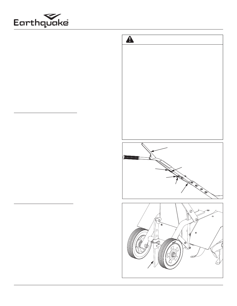
Belt Tension Adjustment
Proper belt tension is critical to good performance. After 1/2
hour of operation, all cables may have to be adjusted due to
initial stretch. Thereafter, check tension after every 2 hours
of operation. Proper tension is achieved when the spring
compresses 1/4” when drive lever is engaged.
To increase belt tension do as follows:
1. Loosen upper jam nut. SEE FIGURE 7
2. Tighten the lower jam nut in 1/8” increments, making
sure not to over adjust the tension.
3. Check adjustment by measuring spring compression
when drive lever is engaged. (Proper spring compression
1/4”)
4. When proper adjustment is achieved, tighten upper jam
nut.
NOTE: This procedure can be repeated until conduit
adjustment bolts are fully adjusted. If no more
adjustment can be made, belt may need to be
replaced.
Drag Stake
Tilling depth is controlled by the height of the (drag stake) depth
regulator lever. SEE FIGURE 8
To adjust tilling depth do as follows:
1. Remove lock pin.
2. Raise the depth regulator lever to position tines at
chosen tilling depth. Lowering the depth regulator will
allow for deeper tilling.
3. Align hole in depth regulator lever with hole in depth
regulator bracket and replace lock pin.
NOTE: Raise depth regulator all the way when
transporting tiller. Lower the depth regulator all
the way to maintain control of the tiller in harder
soil conditions.
WARNING
THIS INFORMATION IS PROVIDED HERE ONLY
TO INTRODUCE THE CONTROLS. DO NOT START
THE ENGINE AT THIS TIME. PLEASE READ THIS
SECTION AND ALL OPERATING AND SAFETY
INSTRUCTIONS BEFORE STARTING YOUR TILLER.
•
AS A SAFETY PRECAUTION, THE DRIVE
SAFETY CONTROL LEVER WILL NOT LOCK IN
THE FORWARD POSITION.
•
TO STOP THE TINES AT ANY TIME RELEASE
THE DRIVE SAFETY CONTROL LEVER.
•
PROTECTIVE FOOTWEAR MUST BE WORN
WHILE OPERATING THIS PRODUCT.
•
ENGINE SHOULD BE OFF BEFORE ADJUSTING
ANY CONTROLS.
•
DO NOT ADJUST TILLING DEPTH UNLESS
DRIVE SAFETY CONTROL LEVER IS RELEASED
TO THE NEUTRAL POSITION.
FAILURE TO FOLLOWS THESE INSTRUCTIONS CAN
CAUSE SERIOUS INJURY OR DEATH.
DRAG STAKE LEVER
FIGURE 8
DRIVE SAFETY CONTROL
LEVER DISENGAGED
SPRING
TENSION NUT
LOWER JAM NUT
FORWARD CABLE
UPPER JAM NUT
FIGURE 7