EarthQuake 26750 User Manual
Page 10
Check for parts online at
www.getearthquake.com or call 800-345-6007 M-F 8-5
10
Operator's Manual
VECTOR™ Compact Tiller
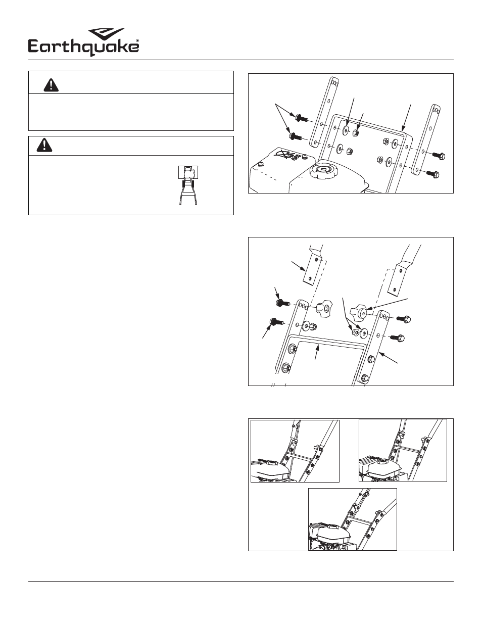
HIGHEST
HANDLEBAR
POSITION
MIDDLE
HANDLEBAR
POSITION
LOWER
HANDLEBAR
POSITION
FIGURE 3
IMPORTANT
THE RIGHT AND LEFT SIDES
O F YO U R ROTOT I L L E R A R E
D E T E R M I N E D F R O M T H E
O P E R AT I N G P O S I T I O N A S
YOU FACE THE DIRECTION OF
FORWARD TRAVEL.
L
R
M8X25 BOLTS
M8 NUTS
M8 WASHERS
LOWER
HANDLEBAR
LOOP
FIGURE 1
UNPACKING AND ASSEMBLY
Unpacking and Assembling Your Tiller
Tools Required for Assembly
•
10 mm Wrench
•
12 mm Wrench
•
(or, two adjustable crescent wrenches)
1. Open top of carton and remove handlebar assembly.
2. Parts bag for VECTOR tiller contains:
•
2- Bolts M8 x 1.25 x 20 Hex Head
•
6- Bolts M8 x 1.25 x 25 Hex Head
•
6- Washers M8 8.4mm x 24mm x 2.2mm
•
6- Nuts M8 x 1.25
•
2- Middle Handlebar Straps
•
2- Hand Knobs
•
6- Bolts M6 x 1.0 x 12
•
6- Nylock Nuts M6 x 1.0
3. Remove machine from carton
4. Assemble the upper handlebar onto the lower handlebar
loop as follows: SEE FIGURES 1 AND 2
a. Use the two (2) middle handlebar straps to connect
the upper handlebar to the lower handlebar loop.
b. Install the M8 x 25 bolts through the six lower bolt
holes from the outside in.
c. Install six (6) washers and tighten with six (6) M8 nuts
on the six (6) bolts.
d. Tighten the two (2) M8 hand knobs on the two (2) M8
x 20 bolts in the upper most hole on each side of the
handlebar. .
NOTE: The two (2) upper bolts and hand knobs can be
used in one of three hole positions for handlebar
height adjustment. SEE FIGURE 3
DO NOT LIFT THE ROTOTILLER FROM THE CARTON.
ROTOTILLER IS HEAVY AND CAN CAUSE INJURY. CUT
BOX AWAY FROM ROTOTILLER AND REMOVE BOX.
WARNING
UPPER
HANDLEBAR
M8-20 BOLTS
M8X25
BOLTS
LOWER
HANDLEBAR
LOOP
HANDLEBAR
STRAP
M8
HAND
KNOB
M8 NUTS &
WASHERS
FIGURE 2