DuraVent DuraStack Installation User Manual
Page 20
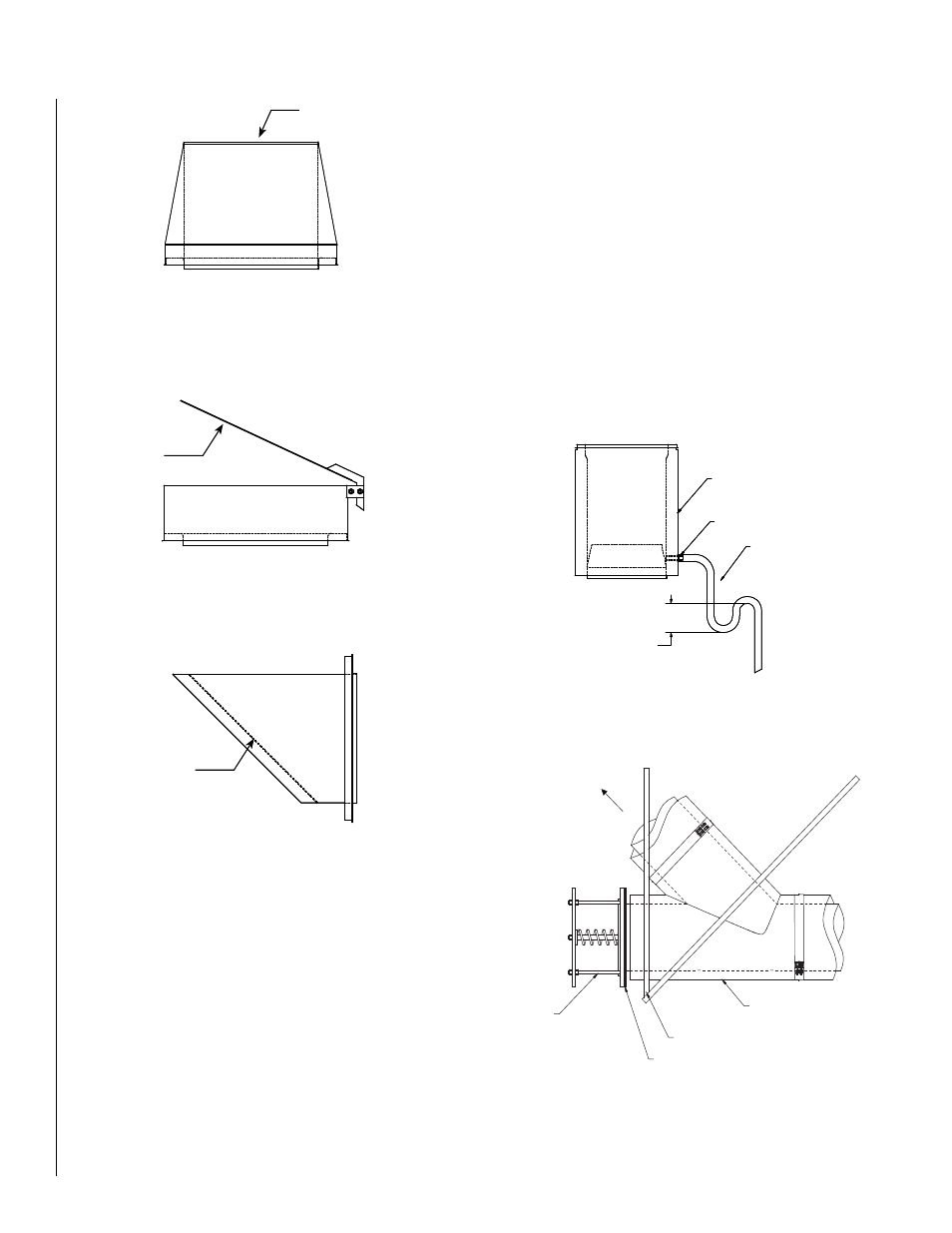
Figure 49 - Drain length
Drain tubing
(by others)
Drain
Drain length
Trap height equal to max
appliance outlet pressure
Figure 50 - Relief Valve installation
Flue direction
Tee 45 RV (T45RV)
Anchor plate (AP)
in frame by others
ANSI Female Flange adaptor (FFA)
Relief valve
NOTE:.DIAGRAMS.&.ILLUSTRATIONS.ARE.NOT.TO.SCALE.
20
DRAIN LENGTH
Drain Length (DL)
1.....Used.to.drain.rain.or.condensate.from.the.chimney.
2.....The.chimney.flue.is.equipped.with.an.annular.catch.ring.and.a.1”.NPT.
nipple.extending.through.the.outer.casing.for.attachment.of.drain.
tubing.
3.....The.drain.tubing.should.include.a.water.trap.of.a.height.at.least.equal.
to.the.maximum.expected.operating.pressure.at.the.appliance.outlet.
to.avoid.allowing.flue.gases.to.vent.through.the.drain..See.Figure 49.
4.....Drain.length.should.be.installed.indoors.to.prevent.freezing.
RELIEF VALVE (DIS ONLY)
Relief Valve (RV)
1.....The.relief.valve.is.intended.for.use.with.diesel.engines.to.provide.extra.
protection.to.the.chimney.in.case.of.a.delayed.ignition.of.backfire.
2.....The.connection.of.the.Relief.valve.and.the.DIS.chimney.is.done.with.
the.use.of.the.ANSI.Female.Flange.Adaptor.(FFA).
3.....The.valve.is.factory.calibrated.to.open.at.27.in..wc.
4.....The.relief.valve.must.be.supported.independently.of.the.rest.of.the.
exhaust.system...The.best.way.to.accomplish.this.is.to.locate.an.
Anchor. Plate. (AP). support. at. the. joint. between. the. ANSI. Flange.
adaptor.and.the.adjacent.fitting..See.Figure 50.
5.....It.is.crucial.that.the.support.be.properly.secured.to.building.structure.
so.that.it.can.withstand.the.forces.generated.in.case.of.delayed.fuel.
ignition.
6.......It.must.be.installed.in.combination.with.a.Tee.45°.Relief.Valve.(T45RV).
Figure 47 - Flip Top (FT)
Figure 48 - Miter Cut Termination (MC)
Flip top
Bird screen
Figure 46 - Finishing Cone (FC)
Better draft