DuraVent DuraStack Installation User Manual
Page 13
NOTE:.DIAGRAMS.&.ILLUSTRATIONS.ARE.NOT.TO.SCALE.
13
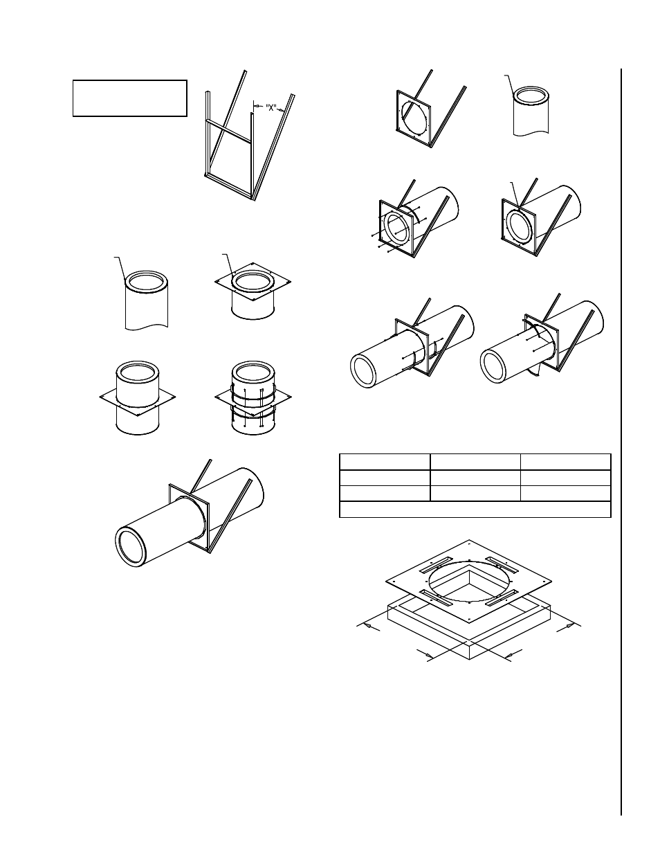
Figure 23 -
Method #1 installation Steps
Sealant
bead
Sealant
bead
Method #1 - Step 1 and 2
Method #1 - Step 3 and 4
Method #1 - Step 5
Method #1 - Step 6
Method #1 - Step 7
Sealant
bead
Method #2 - Step 1
Method #2 - Step 2
Method #2 - Step 5
Method #2 - Step 3 and 4
Method #2 - Step 6 and 7
Method #2 - Step 8
Figure 24 -
Method #2 installation Steps
Figure 25 - Ventilated anchor plate (APV)
I.D. + 8” (DIS)
I.D. + 12” (DAS)
I.D. + 8” (DIS)
I.D. + 12” (DAS)
I.D.
FRAMEWORK
BRACING
5” – 20”
3” X 2” X 3/16”
2” X 2” X 1/4”
22” – 36”
4” X 2” X 1/4”
3” X 3” X 1/4”
Table 12 - Bracing DIS / DAS
Height Limits - See Section A,
Table 6 for maximum support
height of Anchor Plate (AP).
Figure 22 - Homemade brace
NOTE: If bracing is used, mini-
mum “X” angle is 30°. If there
is no bracing, the framework
must be attached to structural
members to provide equivalent
rigidity.