Driverack – dbx Pro 480 User Manual
Page 17
®
RS485 Control Thru Bus (DB-9 connector type)
This Thru network connection is used to pass information to other units in the DriveRack™ net-
work link.
RS485 Control Bus Input (RJ-45 connector type)
This input network connection is used to receive information being sent from other units in the
DriveRack™ network link.
RS485 Control Thru Bus (RJ-45 connector type)
This Thru network connection is used to pass information to other units in the DriveRack™ net-
work link.
Termination LEDs
These LEDS indicate when network is properly terminated. The Green LED indicates that the net-
work has been correctly terminated.
Remote Controller In Connection
This DB-9 type input connection is used to send and receive information from the 480 Remote
DriveRack™ Unit.
PC Connection
This DB-9 type connection is used to send and receive information to and from the GUI interface.
Outputs 1-8
The output section of the 482 DriveRack™ offers eight electronically balanced XLR connectors.
Inputs 1-4
The input section of the 482 DriveRack™ offers four electronically balanced XLR connectors.
Inputs 3 and 4 offer Line/RTA switches that allow you to run a real time audio analyzer micro-
phone directly into the input of the 482 DriveRack™. The four XLR inputs of the 482 DriveRack™
also offer Pin 1 lift switches which lift the ground of the selected XLR input pair when pressed.
Warning - For proper operation of the RTA microphone, the RTA button must be depressed and
the ground /lift switch must be in the grounded position. When the RTA button on the back panel
is depressed, 48V phantom power is applied to pins 2 and 3 of the XLR connector. To maintain
a proper ground return for the phantom power, the ground/lift switch must be in the grounded
position. This will prevent the possibility of electrical shock.
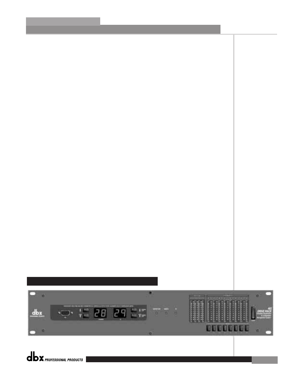
1.6 Front Panel (482)
Getting Started
Section 1
DriveRack
™
7