Driverack – dbx Pro 480 User Manual
Page 12
Getting Started
®
DriveRack™ User Manual
2
Section 1
DriveRack
™
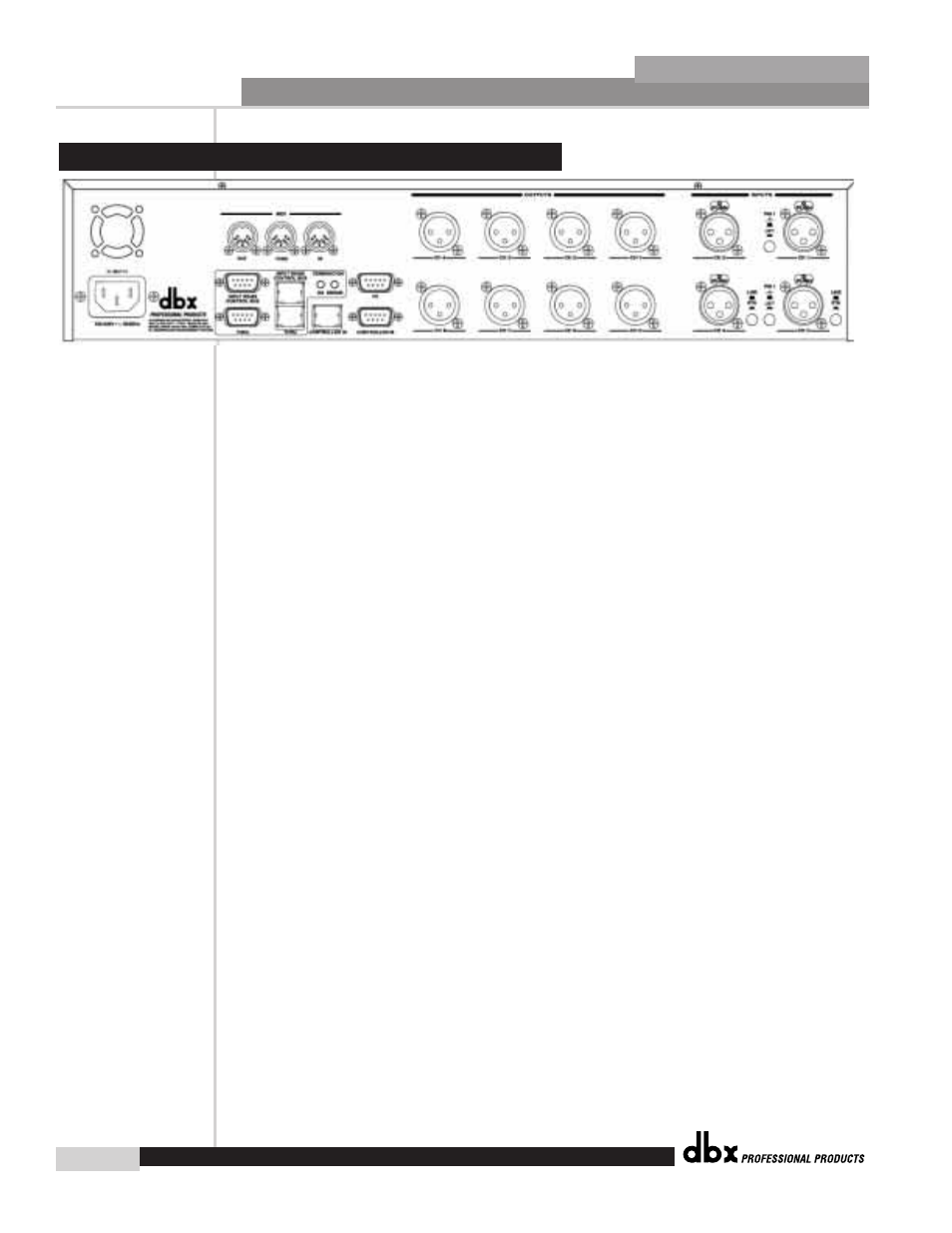
IEC Power Cord Receptacle
The 480 comes with an International power supply that will accept voltages ranging from 100V-
240V at frequencies from 50Hz-60Hz. An IEC cord is included.
MIDI In, Out and Thru Connectors
These connectors provide MIDI functionality to the 480 DriveRack™. The In, Out and Thru jacks
allow you to use the 480 DriveRack™ at any point in the MIDI chain.
RS485 Control Bus Input (DB-9 connector type)
This input network connection is used to receive information being sent from other units in the
DriveRack™ network link.
RS485 Control Thru Bus (DB-9 connector type)
This Thru network connection is used to pass information to other units in the DriveRack™ net-
work link.
RS485 Control Bus Input (RJ-45 connector type)
This input network connection is used to receive information being sent from other units in the
DriveRack™ network link.
RS485 Control Thru Bus (RJ-45 connector type)
This Thru network connection is used to pass information to other units in the DriveRack™ net-
work link.
Termination LEDs
These LEDS indicate when network is properly terminated. The Green LED indicates that the
network has been correctly terminated.
Remote Controller In Connection
This DB-9 type input connection is used to send and receive information from the 480R Remote
Control unit.
PC Connection
This DB-9 type connection is used to send and receive information to and from the GUI inter-
face.
Outputs 1-8
The output section of the 480 DriveRack™ offers eight electronically balanced XLR connectors.
1.1 Rear Panel Connections (480)