14 lvds panel jumpers, Jp3: panel power voltage, Jp4: backlight power voltage – ADLINK nanoX-BASE User Manual
Page 26: Jp20: brightness control, Jp23: brightness pwm source
nanoX-BASE User’s Manual
Page 26
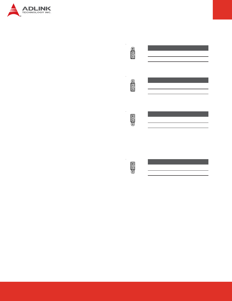
JP3:
Panel Power Voltage
Selects the Panel PWR voltage on
CN7 Backlight Control pin header (pin 2).
Jumper
Status
1-2
+3.3V
<<<<
2-3
+5V
1
2
3
JP4:
Backlight Power Voltage
Selects the Backlight PWR voltage on
CN7 Backlight Control pin header (pin 8).
Jumper
Status
1-2
+12V
2-3
+5V
<<<<
1
2
3
JP20:
Brightness Control
Sets the Panel Brightness Control (CN7 pin 3:
Backlight CTRL) to Voltage Level or PWM .
When set to Voltage Level, the Backlight CTRL
signal can be varied from 0~5V in 0.5V
increments.
Jumper
Status
1-2
Voltage Level <<<<
2-3
PWM
1
2
3
JP23:
Brightness PWM Source
Sets the Panel Brightness PWM Source
to GPU or LVDS I2C. When Brightness PWM
Source is set to LVDS I2C, the user will be able
to use the AIDI Library AidiVgaSetBacklight
command to control the PWM pulse to the
panel backlight.
Jumper
Status
1-2
GPU
2-3
LVDS I2C
<<<<
1
2
3
6.14 LVDS Panel Jumpers
Note:
<<<< indicates default setting