20 other jumper settings, Jp1: lpc port 80, Jp2/jpz5: bios selection – ADLINK Express-BASE User Manual
Page 35: Jp5: cmos clear, Jpy6: tpm signal jumper
Page 35
Express-BASE User’s Manual
6.20 Other Jumper Settings
JP1:
LPC Port 80
Free Run: BIOS will complete the boot process
Single Step: BIOS will execute step-by-step by
pressing SW2 button
Jumper
Status
1-2
Free Run
<<<<
2-3
Single Step
1
2
3
JP2/JPZ5:
BIOS Selection
See 7 Secondary BIOS on page 37 for
a detailed description.
JPZ5
JP2
Status
1-2
1-2
Module BIOS
<<<<
1-2
2-3
Carrier FWH BIOS
2-3
1-2
Carrier SPI BIOS
2-3
2-3
Reserved
1
2
3
NOTE:
<<<< indicates default setting
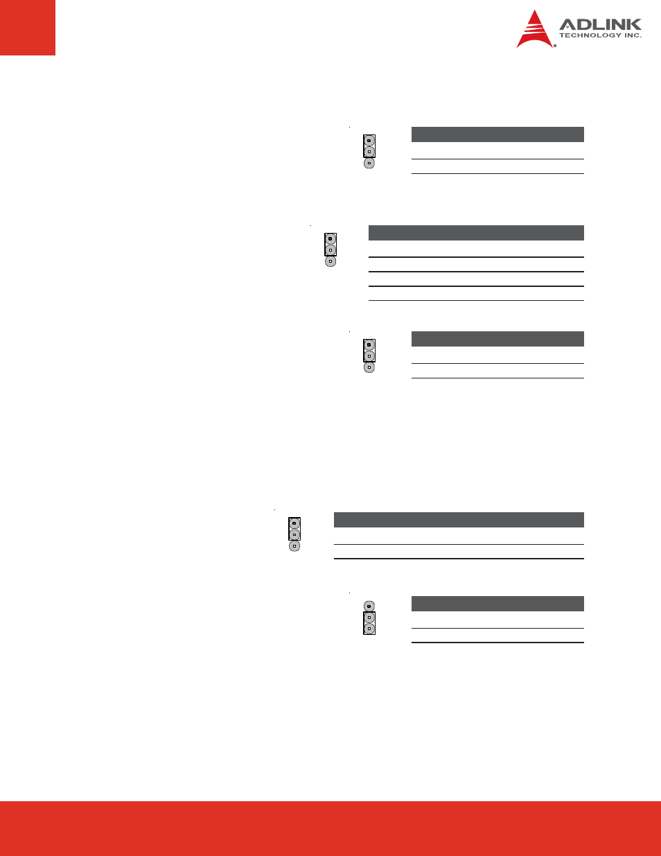
JP5:
CMOS Clear
To clear CMOS, shut down the power and short
pins 2 and 3 (shorts VBAT to ground).
Jumper
Status
1-2
Normal
<<<<
2-3
Clear CMOS
1
2
3
JPY6:
TPM Signal Jumper
Configuring the jumper to "ON" pulls the
TPM signal high and "OFF" does nothing
to the TPM signal. Dependent upon module's
design for the TPM signal.
Jumper
Status
1-2
ON
2-3
OFF
<<<<
1
2
3
JP6:
External PEG/Internal Graphics with SDVO Selection
This jumper controls PCIE7: PCI Express x16 mode and SDVO mode. Enables/disables internal
graphics or external graphics on the x16 PCI Express Graphics (PEG) port. If the PEG port is
enabled, both the internal graphics and SDVO will be disabled.
Jumper
Enable
1-2
Internal Graphics with SDVO
<<<<
2-3
PCI Express x16 slot graphics
1
2
3