19 power jumper settings, Jpy1: at/atx mode, Cny6: pwr_ok config cny7: power up config – ADLINK Express-BASE User Manual
Page 32: Jpy10: ps_on# signal source, Jpz3: at power 5v setting
Express-BASE User’s Manual
Page 32
JPY1:
AT/ATX MODE
In AT mode, JPY1 shorts PS_ON# to ground
directly to force power on.
Jumper
Status
1-2
ATX Mode
<<<<
2-3
AT Mode
1
2
3
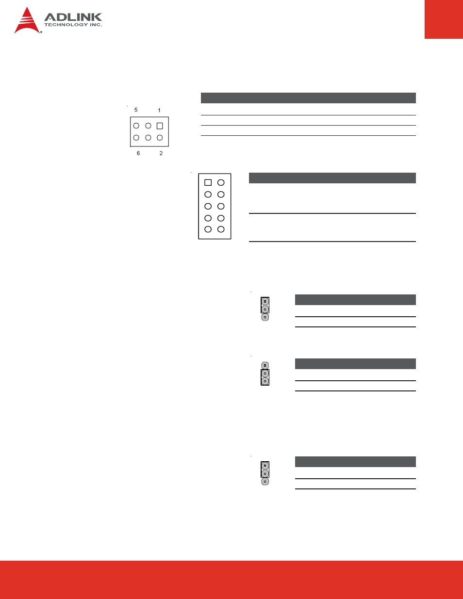
CNY6:
PWR_OK Config
CNY7:
Power Up Config
Jumper
Status
1-10
5-6
Power-up by module
<<<<
8-9
2-9
3-8
Power-up by Super I/O*
4-7
5
10
1
6
Jumper
Status
1-2
Add 3.3V Pullup with 10K to signal PWR_OK
3-4
Connect PWRGOOD of ATX power supply
<<<<
5-6
Connect PWRGOOD of onboard DCDC regulator
*The Super I/O detects a power button event using the 'PSIN' pin. When a power button event occurs, the power-
up logic of the Super I/O sets 'PSOUT#' low and asserts 'PWRBTN#' of the module's chipset. The Super I/O also
sets the 'PWRCTL#' pin to low, which asserts the 'PS_ON#' signal and switches on the ATX power supply.
NOTE:
<<<< indicates default setting
6.19 Power Jumper Settings
JPY10: PS_ON# Signal Source
Jumper
Status
1-2
SUS_S3#
<<<<
2-3
SUS_S5#
1
2
3
All ADLINK modules support S3 mode and
consecutive power down of ATX power supply.
For modules that connect the S3 signal, PS_ON#
should always be set to SUS_S3# as source (even when S3 mode is disabled in the BIOS). For
modules that do not bring out the S3 signal, PS_ON# should be set to SUS_S5# as source.
JPZ3:
AT Power 5V Setting
With an AT power supply is connected to
the Express-BASE, JPZ3 can be used to
provide 5VSB to the COM module from
the carrier board.
Jumper
Status
1-2
AT without P5V
<<<<
2-3
AT with P5V
1
2
3