Smbus, I2c bus, General purpose i/o (gpio) – ADLINK Express-IBE2 User Manual
Page 24
Page 24
Express-IBE2
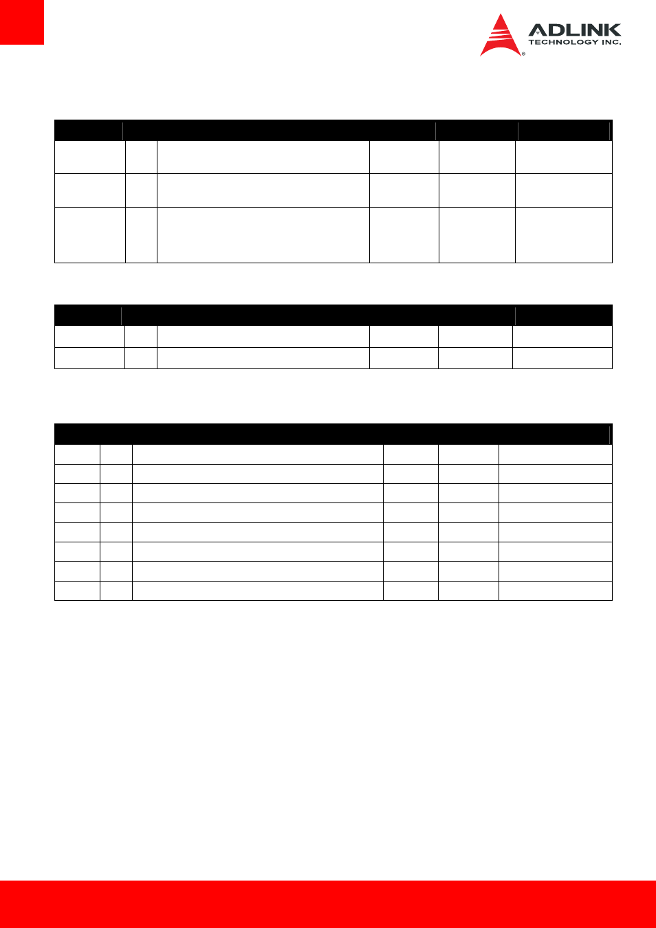
3.3.12. SMBus
Signal
Pin
Description
I/O
PU/PD
Comment
SMB_CK
B13
System Management Bus bidirectional clock line. Power
sourced through 5V standby rail and main power rails.
I/O OD 3.3VSB
PU 2k2 3.3VSB
SMB_DAT#
B14
System Management Bus bidirectional data line. Power
sourced through 5V standby rail and main power rails.
I/O OD 3.3VSB
PU 2k2 3.3VSB
SMB_ALERT#
B15
System Management Bus Alert – active low input can
be used to generate an SMI# (System Management
Interrupt) or to wake the system. Power sourced
through 5V standby rail and main power rails.
I 3.3VSB
PU 10k 3.3VSB
3.3.13. I2C Bus
Signal
Pin
Description
I/O
PU/PD
Comment
I2C_CK
B33
General purpose I²C port clock output/input
I/O OD 3.3VSB
PU 2k2 3.3VSB
I2C_DAT
B34
General purpose I²C port data I/O line
I/O OD 3.3VSB
PU 2k2 3.3VSB
3.3.14. General Purpose I/O (GPIO)
Signal
Pin
Description
I/O
PU/PD
Comment
GPO[0]
A93
General purpose output pins.
O 3.3V
GPO[1]
B54
General purpose output pins.
O 3.3V
GPO[2]
B57
General purpose output pins.
O 3.3V
GPO[3]
B63
General purpose output pins.
O 3.3V
GPI[0]
A54
General purpose input pins. Pulled high internally on the module.
I 3.3V
PU 10K 3.3V
GPI[1]
A63
General purpose input pins. Pulled high internally on the module.
I 3.3V
PU 10K 3.3V
GPI[2]
A67
General purpose input pins. Pulled high internally on the module.
I 3.3V
PU 10K 3.3V
GPI[3]
A85
General purpose input pins. Pulled high internally on the module.
I 3.3V
PU 10K 3.3V