3 lvds, 4 gigabit ethernet – ADLINK Express-HLE User Manual
Page 17
Express-HLE
Page 17
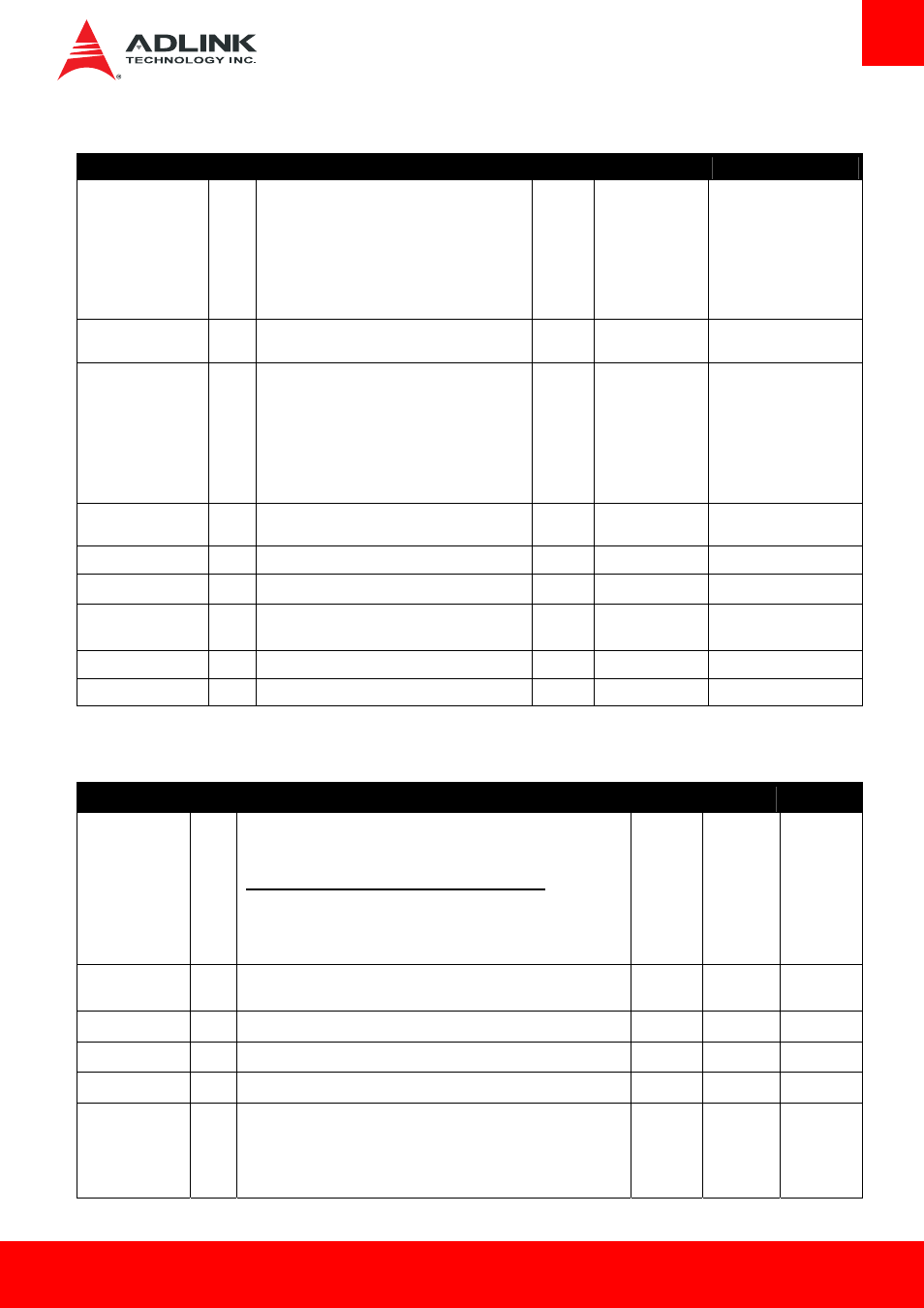
3.3.3
LVDS
Signal
Pin #
Description
I/O
PU/PD
Comment
LVDS_A0+
LVDS_A0-
LVDS_A1+
LVDS_A1-
LVDS_A2+
LVDS_A2-
LVDS_A3+
LVDS_A3-
A71
A72
A73
A74
A75
A76
A78
A79
LVDS Channel A differential pairs
O LVDS
LVDS_A_CK+
LVDS_A_CK-
A81
A82
LVDS Channel A differential clock
O LVDS
LVDS_B0+
LVDS_B0-
LVDS_B1+
LVDS_B1-
LVDS_B2+
LVDS_B2-
LVDS_B3+
LVDS_B3-
B71
B72
B73
B74
B75
B76
B77
B78
LVDS Channel B differential pairs
O LVDS
LVDS_B_CK+
LVDS_B_CK-
B81
B82
LVDS Channel B differential clock
O LVDS
LVDS_VDD_EN
A77
LVDS panel power enable
O 3.3V
LVDS_BKLT_EN
B79
LVDS panel backlight enable
O 3.3V
LVDS_BKLT_CTRL
B83
LVDS panel backlight brightness control
O 3.3V
PD 100K
Realtek ePD to LVDS
requirement
LVDS_I2C_CK
A83
DDC lines used for flat panel detection and control. O 3.3V
PU 2k2 3.3V
LVDS_I2C_DAT
A84
DDC lines used for flat panel detection and control. I/O 3.3V
PU 2k2 3.3V
3.3.4
Gigabit Ethernet
Gigabit Ethernet
Pin #
Description
I/O
PU/PD
Comment
GBE0_MDI0+
GBE0_MDI0-
GBE0_MDI1+
GBE0_MDI1-
GBE0_MDI2+
GBE0_MDI2-
GBE0_MDI3+
GBE0_MDI3-
A13
A12
A10
A9
A7
A6
A3
A2
Gigabit Ethernet Controller 0: Media Dependent Interface Differential Pairs
0, 1, 2, 3. The MDI can operate in 1000, 100, and 10Mbit/sec modes.
Some pairs are unused in some modes according to the following:
1000BASE-T
100BASE-TX
10BASE-T
MDI[0]+/- B1_DA+/-
TX+/- TX+/-
MDI[1]+/- B1_DB+/-
RX+/- RX+/-
MDI[2]+/- B1_DC+/-
MDI[3]+/- B1_DD+/-
I/O Analog
Twisted pair
signals for
external
transformer.
GBE0_ACT#
B2
Gigabit Ethernet Controller 0 activity indicator, active low.
O 3.3VSB
PU 10k
3.3VSB
GBE0_LINK#
A8
Gigabit Ethernet Controller 0 link indicator, active low.
O 3.3VSB
GBE0_LINK100#
A4
Gigabit Ethernet Controller 0 100Mbit/sec link indicator, active low.
O 3.3VSB
GBE0_LINK1000# A5
Gigabit Ethernet Controller 0 1000Mbit/sec link indicator, active low.
O 3.3VSB
GBE0_CTREF
A14
Reference voltage for Carrier Board Ethernet channel 1 and 2 magnetics
center tap. The reference voltage is determined by the requirements of the
Module PHY and may be as low as 0V and as high as 3.3V. The reference
voltage output shall be current limited on the Module. In the case in which
the reference is shorted to ground, the current shall be 250 mA or less.
GND min
3.3V max