2 continuous acquisition mode, 6 programmable function i/o, 1 ttl di/do – ADLINK USB-2401 User Manual
Page 47: Continuous acquisition mode, Programmable function i/o, Ttl di/do, Table 3-3: ttl digital i/o pin definition
Operation
37
USB-2401
completed. Please refer to UD-DASK function reference for the
details of corresponding software API instruction.
3.5.2
Continuous Acquisition Mode
Differs from software polling mode only in the generation of block
data in continuous acquisition mode without the need to consider
data overwriting or acquiring repeat data in software polling mode.
This mode is suitable for when continuous data is to be acquired in
a fixed and precise time interval. Please note the data buffer size
must be a multiple of 128 in continuous acquisition mode. Please
refer to UD-DASK function reference for details of corresponding
software API instruction.
3.6
Programmable Function I/O
The USB-2401 supports powerful programmable I/O function pro-
vided by an FPGA chip, configurable as TTL DI/DO, 32-bit
timer/counters, and PWM output. These signals are single-ended
and 5V TTL-compliant.
3.6.1
TTL DI/DO
Programmable function I/O can be used as static TTL-compliant
4-CH digital input and 2-CH digital output. The I/O lines can be
updated by software polling, with sample and update rate fully
controlled by software timing.
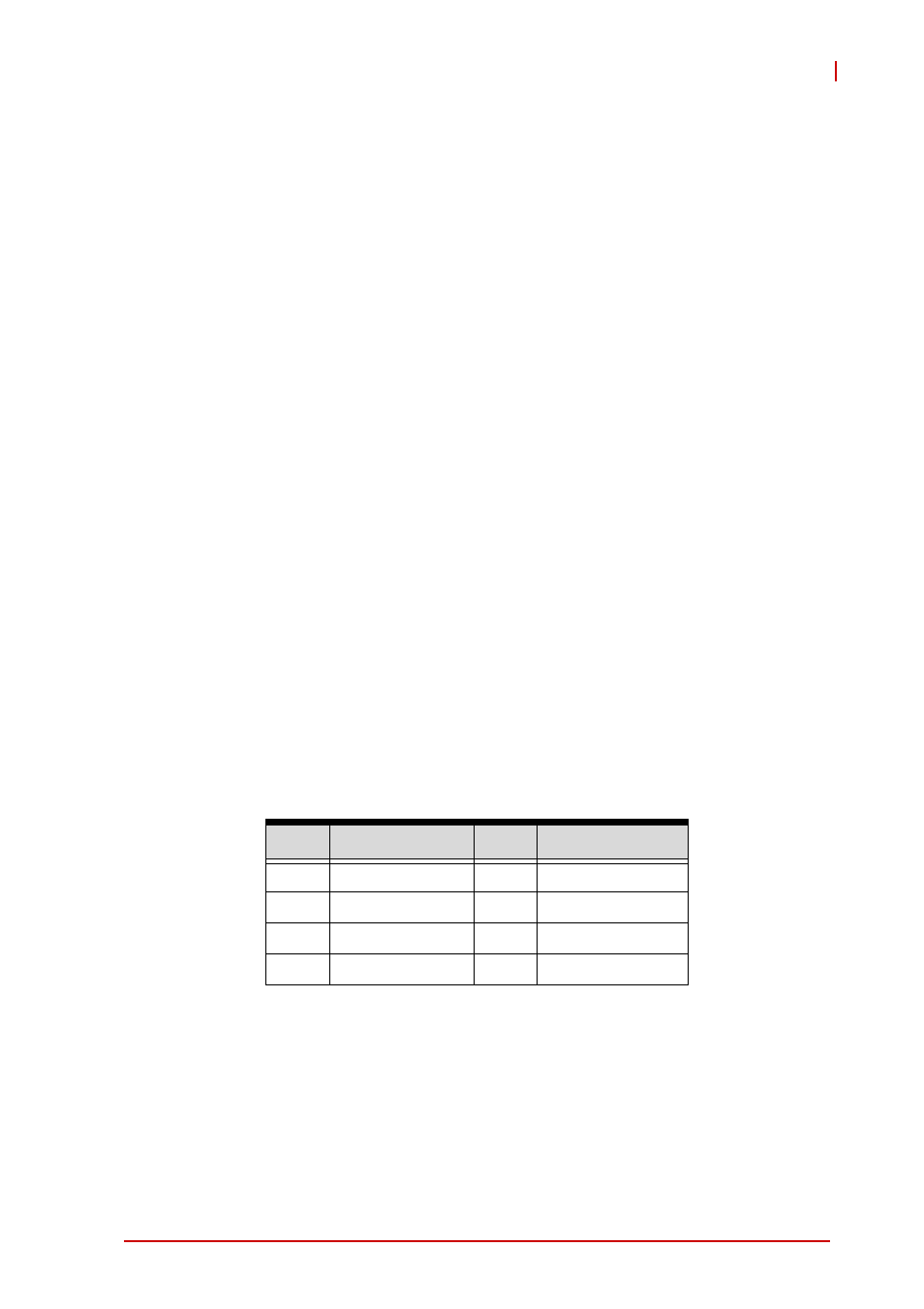
Table 3-3: TTL Digital I/O Pin Definition
Pin
Function
Pin
Function
20
GPO0
40
GPO1
19
GPI1
39
GPI3
18
GPI0
38
GPI2
17
NC
37
DGND