3 rs-485 terminator (jp2 & jp3), 12 hard disk controller (cn6), Rs-485 terminator (jp2 & jp3) -9 – Acrosser AR-B1320 User Manual
Page 29: Hard disk controller (cn6) -9
A
A
R
R
-
-
B
B
1
1
3
3
2
2
0
0
U
U
s
s
e
e
r
r
’
’
s
s
G
G
u
u
i
i
d
d
e
e
3.11.3
RS-485 TERMINATOR (JP2 & JP3)
JP2 & JP3 are used to enable the RS-485 terminator resistor of COM-A and COM-B port
respectively. The value of the terminator resistor is 150 ohms. Close the jumper to enable the
RS-485 terminator and leave the jumper open to disable it.
COM Port
Jumper
When “Open”
When “Close”
Factory Preset
COM-A JP2 Disabled Enabled
Open
COM-B JP3 Disabled Enabled
Open
Table 3-7 JP2 & JP3: RS-485 Terminator
3.12
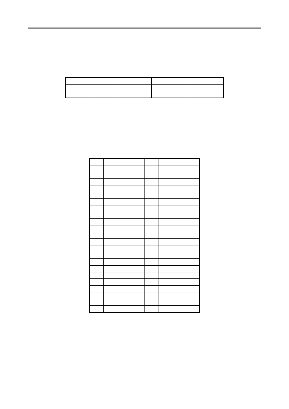
HARD DISK CONTROLLER (CN6)
A 44-pin header type connector (CN6) is provided to interface with up to two embedded hard disk
drives (IDE AT bus). This interface, through a 44-pin cable, allows the user to connect up to two
drives in a "daisy-chain" fashion. To enable or disable the hard disk controller, please use the
BIOS Setup program. The following table illustrates the pin assignments of the hard disk drive's
44-pin connector.
Pin Function Pin
Function
1 -Reset 2 Ground
3
Data 7
4
Data 8
5
Data 6
6
Data 9
7
Data 5
8
Data 10
9
Data 4
10
Data 11
11
Data 3
12
Data 12
13
Data 2
14
Data 13
15
Data 1
16
Data 14
17
Data 0
18
Data 15
19 Ground 20
Not
used
21 Not
used 22
Ground
23 -IOW 24
Ground
25 -IOR 26
Ground
27 Not
used 28
BALE
29 Not
used 30
Ground
31 IRQ
14 32
-IOCS16
33 SA1 34
Not
used
35 SA0 36
SA2
37 -CS0 38
-CS1
39 Hard
disk
LED 40
Ground
41
VCC (+5V)
42
VCC (+5V)
43 Ground 44
Not
used.
Table 3-8 CN6: IDE Connector
3-9