2 system settings, 1 lcd1 (lcd connector) – Acrosser AR-B1622 User Manual
Page 6
AR-B1622 User’s Guide
6
2.2 SYSTEM SETTINGS
Jumper pins allow you to set specific system parameters. Set them by changing the pin location of the jumper
blocks. (A jumper block is a small plastic-encased conductor that slips over the pins.) To change a jumper
setting, remove the jumper from its current location with your fingers or small needle-nosed pliers. Place the
jumper over the two pins designated for the desired setting. Press the jumper evenly onto the pins. Be careful
not to bend the pins.
We will show the locations of the AR-B1622 jumper pins, and the factory-default settings.
CAUTION: Do not touch any electronic components unless you are safely grounded. Wear a
grounded wrist strap or touch an exposed metal part of the system unit chassis. The static discharges
from your fingers can permanently damage electronic components.
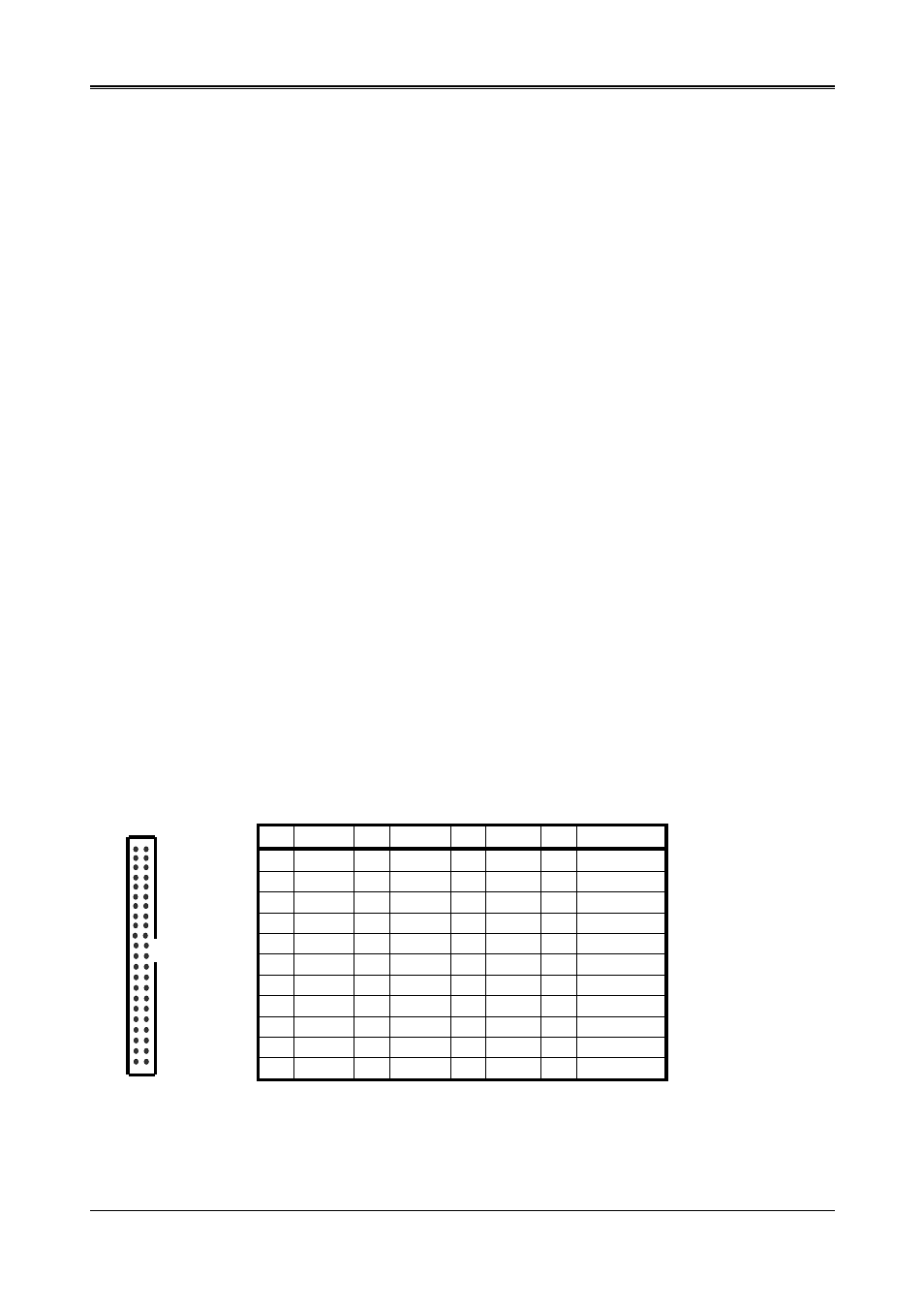
2.2.1 LCD1 (LCD CONNECTOR)
PIN DEFINE PIN DEFINE PIN DEFINE PIN
DEFINE
1 GND 2
FPCLK
23
D14 24
D15
3 GND 4
HSYNC
25
D16 26
D17
5 VSYNC 6 GND 27
GND 28
D18
7 D0 8 D1 29
D19
30
D20
9 D2 10 D3 31
D21
32
D22
11
D4 12 D5 33
D23
34
GND
13
GND 14 D6 35
LCDVDD
36
LCDVDD
15
D7 16 D8 37
12V
38
12V
17
D9 18 D10 39
GND
40
GND
19
D11 20 GND 41
DE 42
LVDS_BKLTEN
21
D12 22 D13 43
GND 44
ENVDD
2 1
44 43