Gpi / gpo connector definition, Gpi o2 / com4 pin definition pcba, Db15 – Acrosser AES-HM76Z1FL User Manual
Page 48: Gpio1 / com3 pin definition pcba
48
6.5. USB
There are three USB 3.0 connectors on the main board. USB 3.0 signals are compatible with
USB 2.0 signals. You can connect USB 3.0 or 2.0 devices without any problems. There
are also two USB 2.0 signals used by mini-PCIe and combo USB interface.
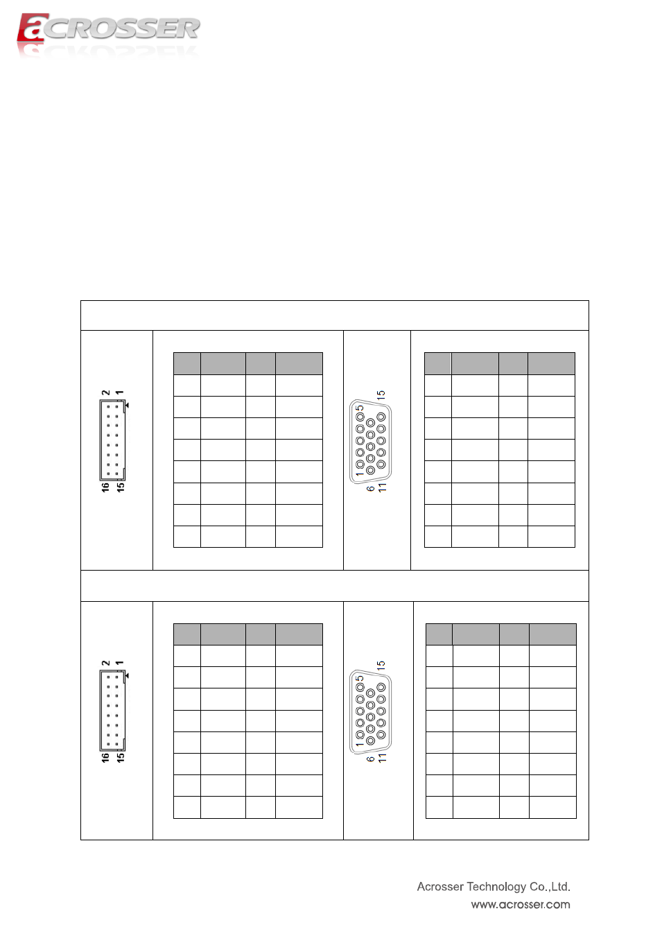
6.6. GPI / GPO connector definition
GPI O2 / COM4 pin definition
PCBA
PIN
SIGNAL
PIN
SIGNAL
1
GPI0
2
GPI1
3
GPI2
4
GPI3
5
GND
6
GND
7
TX4+
8
TX4-
9
RX4+
10
RX4-
11
GPI4
12
GPI5
13
GPI6
14
GPI7
15
Reserved
16
NC
DB15
PIN
SIGNAL
PIN
SIGNAL
1
GPI0
2
GPI1
3
GPI2
4
GPI3
5
GND
6
GND
7
TX4+
8
TX4-
9
RX4+
10
RX4-
11
GPI4
12
GPI5
13
GPI6
14
GPI7
15
Reserved
N/A
N/A
GPIO1 / COM3 pin definition
PCBA
PIN
SIGNAL
PIN
SIGNAL
1
GPO0
2
GPO1
3
GPO2
4
GPO3
5
GND
6
GND
7
TX3+
8
TX3-
9
RX3+
10
RX3-
11
GPO4
12
GPO5
13
GPO6
14
GPO7
15
Reserved
16
NC
DB15
PIN
SIGNAL
PIN
SIGNAL
1
GPO0
2
GPO1
3
GPO2
4
GPO3
5
GND
6
GND
7
TX3+
8
TX3-
9
RX3+
10
RX3-
11
GPO4
12
GPO5
13
GPO6
14
GPO7
15
Reserved
N/A
N/A