Rules for safe operation (continued), Assembly instructions – Bolens TMO-37478A User Manual
Page 6
Attention! The text in this document has been recognized automatically. To view the original document, you can use the "Original mode".
Rules for Safe Operation (Continued)
BLADE BRAKE/CLUTCH MAINTENANCE
NOTE:
Any required repair work on the blade brake/clutch should be
performed by an authorized service dealer. If you cannot locate an
authorized service dealer, contact the manufacturer.
1. The blade brake/clutch hand control is a safety device. Never
attempt to bypass its operation.
Doing so makes the safety device
inoperative and may result in personal injury through contact with
the rotating blade. This hand control must operate freely in both
directions.
2.
Striking a solid object can cause damage to the blade brake/clutch
or to the engine crankshaft. Extensive vibration of the mower during
operation is an indication of damage and the unit should be
promptly inspected and repaired.
3. A leak in the lower engine crankshaft oil seal could expose the
blade brake/clutch friction pads to excess oil resulting in blade
or brake slippage, which could increase the stopping time of the
blade. Oil collection on the floor beneath the mower dunng storage
may be an indication of an oil seal leak. The unit should be checked
by an authorized service dealer.
4, Periodically inspect the inner control cable in the area where it
attaches to the hand control. If the cable becomes frayed, it could
cause the blade brake/clutch to operate improperly. Also, be careful
to avoid pinching the blade brake/clutch control cable when stor
ing the handle.
IMPORTANT: This unit is shipped WITHOUT GASOLINE or OIL. After assembly, service engine with
gasoline and oil as instructed in the separate engine manual packed with your unit.
NOTE: Reference to right or left hand side of the mower is observed from the operating posi
tion. Refer to parts identification illustration on page 4 for location of parts when assem
bling the mower.
ASSEMBLY INSTRUCTIONS
Tools Required for Assembly
(1) Pair of Pliers
(1) Phillips Head Screwdriver
(1) 1/2" Wrench*
(1) 5/16" Wrench or Nutdriver*
(1) 7/16" Wrench*
*Or one 6" Adjustable Wrench.
UNPACKING
1. Remove the lawn mower from the carton by open
ing the top flaps and lifting the unit out. Be careful
of the staples. Make certain all parts and literature
have been removed from the carton before the car
ton is discarded.
2. Disconnect and ground the spark plug wire against
the engine. Check beneath the deck for any card
board packaging. Remove if present.
3. Stretch out all control cables and place on the floor.
Be careful not to bend or kink the cables at any
time during assembly.
4. Remove page four from this manual and lay the
contents of the hardware pack on the illustration
for identification.
ATTACHING THE LOWER HANDLE (Hardware A)
1. For shipping purposes your mower is set with the
wheels in the lowest cutting height position. Raise
the mower to the highest setting for assembly of
lower handle.
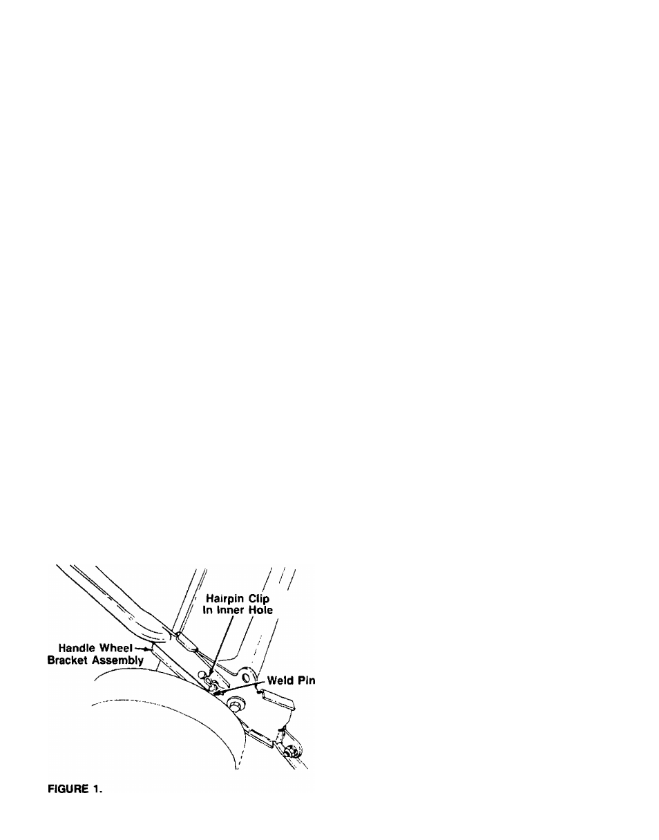
2. Attach the lower handle by placing the bottom
holes in the lower handle over the weld pins on the
handle wheel bracket assemblies on the rear of the
deck. Make certain the instruction label on the
lower handle can be read from the operating
position.
—3. Using a pair of pliers, squeeze one leg of the lower
handle against the handle wheel bracket assembly.
Insert the hairpin clip into the inner hole on the
weld pin. See figure 1. Repeat on other side.