Controls, Figure 7, Throhle control – Bolens 13AG678G022 User Manual
Page 8: Choke control, Shift lever, Speed control lever, Ignition switch, M meter optional), Figure 8, Light switch (optional)
Attention! The text in this document has been recognized automatically. To view the original document, you can use the "Original mode".
CONTROLS
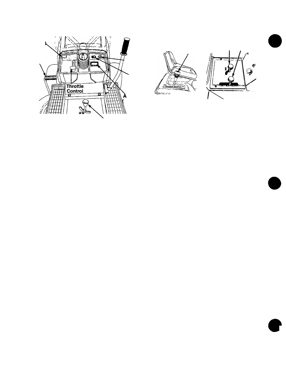
Choke
Contro
Clutch-Brake
Pedal
FIGURE 7.
Shift Lever
THROHLE CONTROL
The
throttle
control
is
used
to
regulate
the
engine
speed.
To
get
maximum
efficiency
from
cutting,
the
throttle should be in the FAST position when operating
the mower. See figure 7.
CHOKE CONTROL
The choke control is located on the dashboard and is
operated manually. Details for the choke operation are
covered
in
the
separate
engine
manual
packed
with
your unit. See figure 7.
SHIFT LEVER
The shift lever is located in the center of the console
and
has
three
positions,
FORWARD,
NEUTRAL
and
REVERSE. See figure 8. The clutch-brake pedal must
be depressed and the lawn tractor must not be moving
when
shifting
gears.
Do
not
force
the
shift
lever.
Release the clutch-brake pedal slightly to line up the
shifting
collar
in
the
transmission.
Then
try
to
shift
gears.
SPEED CONTROL LEVER
The speed control lever is located either on the con
sole or on the right fender. See figure 8. The speed
control lever allows you to regulate the ground speed
of
the
lawn
tractor.
To
select
the
ground
speed,
depress clutch pedal. Move speed control lever out of
the notches and backward to slow lawn tractor, forward
to
increase
speed.
When
desired
speed
has
been
obtained,
release
lever
in
that
position.
Whenever
clutch is released, unit will automatically go to the pre
set speed.
IGNITION SWITCH
The engine is started by turning the key to the START
position. After the engine starts, let the key return to
the ON position. To stop the engine, turn the key to the
left to the OFF position and remove it to prevent acci
dental starting. See figure 7.
Speed
Control
Lever
Ignition
Switch
Light
Switch
(Optional)
m meter
Optional)
Speed
Shift Control
Lever Lever
FIGURE 8.
LIGHT SWITCH (Optional)
Push the light switch to turn on the lights. The lights
will only operate when the engine is running.
NOTE: If your unit is not equipped with a light switch,
the lights will be on when the engine is running.
AMMETER (Optional)
The ammeter registers the rate of battery charge or
discharge. The ammeter will register on the discharg
ing side when starting the engine. It should register on
the opposite side (charging) when the engine is run
ning in the fast position until the battery is completely
charged.
With
a
fully
charged
battery
or
with
the
engine idling, the ammeter will not show a charge. See
figure 7.
CLUTCH-BRAKE PEDAL
The clutch-brake pedal is located on the left side of the
lawn
tractor.
Depressing
the
clutch-brake
pedal
part
way disengages the clutch. Pressing the pedal all the
way down disengages the clutch and engages the disc
brake. See figure 7.
NOTE: The clutch-brake pedal must be depressed to
start the engine.
PARKING BRAKE
The speed control lever is used to set the parking
brake. To set the parking brake, depress the clutch-
brake pedal. Move the speed control lever out of the
notches
to
the
parking
brake
position.
Release
the
speed control lever and the clutch-brake pedal.
To release the parking brake, depress the clutch-brake
pedal and move the speed control lever out of the
notches
to
the
desired
position.
Release
the
speed
control lever and the clutch-brake pedal.
NOTE: The parking brake must be set if the operator
leaves the seat with the engine running.
INTERLOCKS (Not Shown)
Interlock
safety
switches
are
located
by
the
clutch-
brake pedal, the lift lever, the shift lever and under the
seat.