Wheel adjustment, Carburetor adjustment, Brake adjustment (see figure 15) – Bolens 13AG678G022 User Manual
Page 13: Lubrication
Attention! The text in this document has been recognized automatically. To view the original document, you can use the "Original mode".
't
WHEEL ADJUSTMENT
The caster (forward slant of the king pin) and the
camber (tilt of the wheels out at the top) require no
adjustment.
Automotive
steering
principles
have
been
used
to
determine
the
caster
and
camber
on
the
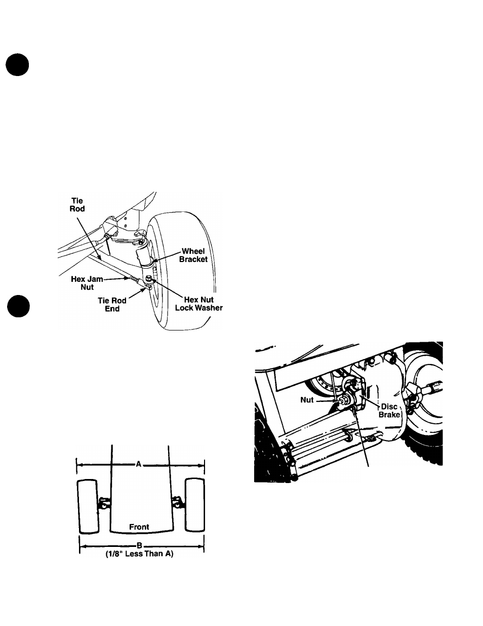
tractor. The front wheels should toe-in 1/8 inch.
Some units have adjustable tie rods so the toe-in can
be adjusted. To adjust the toe-in on these units, pro
ceed as follows.
1.
Remove the hex nut and lock washer, and drop
the tie rod end from the wheel bracket. See figure
13.
2. Loosen the hex jam nut on tie rod.
3. Adjust the tie rod assembly for correct toe-in.
FIGURE 13.—Units with adjustabie tie rods
Dimension “B” should be approximately 1/8" less than
Dimension “A.” See figure 14.
A.
) To increase Dimension “B,” screw tie rod into tie
rod end.
B.
) To decrease Dimension “B,” unscrew tie rod from
tie rod end.
C.
) Reassemble tie rod. Check dimensions. Readjust
if necessary.
CARBURETOR ADJUSTMENT
A
WARNING: If any adjustments are made to
the engine while the engine is running
(e.g. carburetor), disengage ail clutches
and blades. Keep clear of all moving
parts. Be careful of heated surfaces and
muffler.
Minor carburetor adjustment may be required to
compensate for differences in fuel, temperature,
altitude and load.
To adjust the carburetor, refer to the
separate engine manual packed with your unit.
NOTE: A dirty air cleaner will cause an engine to run
rough. Be certain air cleaner is clean and attached to
the carburetor before adjusting carburetor.
BRAKE ADJUSTMENT (See figure 15)
The brake is located by the right rear wheel inside the
frame.
During
normal
operation
of
this
machine,
the
brake
is
subject
to
wear
and
will
require
periodic
examination and adjustment.
A
WARNING: Do not have the engine run
ning when you adjust the brake.
To adjust the brake, adjust the nut so the brake starts
to engage when the brake lever is 1/4" to 5/16" away
from the axle housing.
Brake
Lever
FIGURE 15.
LUBRICATION
A
FIGURE 14.—Units with adjustable tie rods
WARNING: Always stop engine and dis
connect spark plug wire before cleaning,
lubricating or doing any kind of work on
lawn tractor.
13