Optional field-installed electric heat packages – Bryant 517G User Manual
Page 7
Attention! The text in this document has been recognized automatically. To view the original document, you can use the "Original mode".
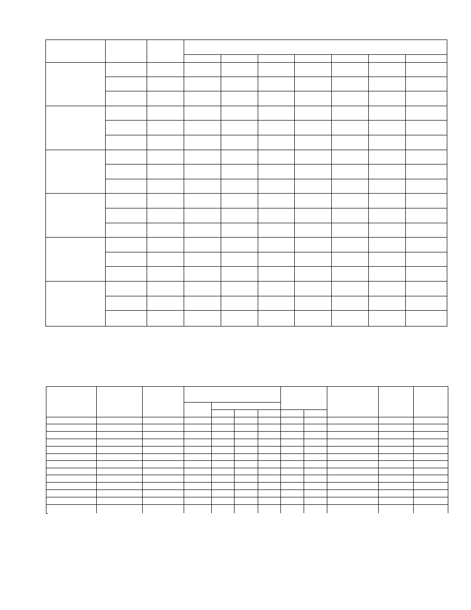
AIR DELIVERY (Ft^/Min) AT INDICATED EXTERNAL STATIC PRESSURE (With Filter)
517E
Size
Motor
Speed
Tap
Coil
-
External Static Pressure —Inches wc
0.1
0.2
0.3
0.4
0.5
0.6
0.7
042
High
Dry
1760
1700
1625
1535
1450
1350
1225
(Without Heater)
Wet
1690
1625
1545
1455
1355
1260
—
Medium
Dry
1615
1545
1490
1415
1345
1255
1150
Wet
1545
1495
1435
1365
1275
1185
—
Low
Dry
1435
1385
1340
1280
1210
1135
1035
Wet
1395
1350
1300
1235
1165
1080
—
042
High
Dry
1700
1635
1560
1475
1395
1290
—
(With Heater)
Wet
1625
1565
1485
1415
1320
1200
—
Medium
Dry
1565
1505
1450
1385
1305
1215
—
Wet
1510
1450
1390
1320
1235
1150
—
Low
Dry
1410
1360
1315
1250
1180
1100
—
Wet
1370
1325
1270
1205
1135
—
—
048
High
Dry
2075
1995
1910
1830
1745
1655
1550
(Without Heater)
Wet
1950
1870
1795
1725
1645
1555
1455
Medium
Dry
1900
1830
1765
1700
1625
1545
1450
Wet
1810
1745
1685
1615
1540
1455
—
Low
Dry
1710
1665
1615
1565
1510
1450
1370
Wet
1660
1615
1565
1515
1450
1385
—
048
High
Dry
1970
1905
1825
1755
1675
1580
1490
(With Heater)
Wet
1875
1800
1740
1660
1580
1490
1400
Medium
Dry
1830
1770
1705
1635
1560
1485
—
Wet
1750
1690
1630
1560
1485
1400
—
Low
Dry
1670
1625
1580
1525
1470
1405
—
Wet
1620
1575
1525
1470
1390
—
_
060
High
Dry
2315
2280
2240
2200
2155
2115
2065
(Without Heater)
Wet
2250
2215
2165
2140
2095
2045
1990
Medium
Dry
2125
2080
2040
1995
1950
1905
1850
Wet
2065
2025
1990
1945
1900
1850
1790
Low
Dry
1900
1870
1840
1805
1770
1730
1690
Wet
1860
1830
1800
1760
1730
1680
1650
060
High
Dry
2265
2230
2190
2145
2100
2060
2010
(With Heater)
Wet
2210
2170
2130
2085
2045
2000
1950
Medium
Dry
2070
2035
1995
1955
1915
1870
1820
Wet
2025
1985
1945
1910
1865
1820
1765
Low
Dry
1875
1850
1820
1785
1750
1710
1665
Wet
1850
1815
1780
1750
1715
1675
1625
OPTIONAL FIELD-INSTALLED ELECTRIC HEAT PACKAGES*
Heater
P/N
517E
Sizes
Used
Witht
Heater
Volts-
Phase
(60 Hz)t
Nominal Heater KW
@ 240V**
Heater
Capacity
(MBtuh)**
Internal
Circuit
Protection
Provided
Supply
Circuit
Options
Approx
Ship.
Wt
(lbs)
Total
KW/Stage
1st
2nd
3rd
208V
230V
305971-451
042, 048, 060
208/230-1
7.5
7.5
—
—
19.2
23.5
None
Single
13
305971-452
042, 048, 060
208/230-1
10
10
—
25.6
31.3
None
Single
13
305971-453
042, 048, 060
208/230-1
10
10
—
—
25.6
31.3
Ckt Brkr
Single
14
305971-470
042, 048, 060
208/230-3
10
6.66
3.33
_
25.6
31.3
None
Single
14
305971-471
042, 048, 060
208/230-1
12
8
4
—
30.8
37.6
Fuses
Duaitt
15
305971-472
042, 048, 060
208/230-1
15
10
5
—
38.5
47.0
Fuses
Dualtt
15
305971-473
042, 048, 060
208/230-1
15
10
5
—
38.5
47.0
Ckt Brkr
Dual
15
305971-474
042, 048, 060
208/230-3
15
10
5
—
38.5
47.0
None
Single
15
305971-475
042, 048, 060
208/230-3
18
12
6
—
46.1
56.4
None
Single
15
305971-476
042, 048, 060
208/230-1
20
10
10
—
51.3
62.7
Fuses
Duaitt
17
305971-477
042, 048, 060
208/230-1
20
10
10
—
51.3
62.7
Ckt Brkr
Dual
17
305971-478tt
048, 060
208/230-3
25
8.33
8.33
8.33
64.1
78.4
Fuses
Single
20
305971-479tt
048, 060
208/230-3
30
10
10
10
76.9
86.0
Fuses
Single
20
♦Refer to the appropriate unit/factory-installed heater combinations in the specifications tabies in this PDS for the eiectrical appiication data for these
heat packages.
fAli heat packages are used with Modei 517G Fan Units.
^Operating voitage range is 187—253V.
**KW vaiues shown are nominai rated heater outputs at 240V. Capacity vaiues shown are caicuiated using nominai KW outputs.
ttThese heaters are fieid-convertibie for singie-phase operation by moving two factory high-voltage wires.
ttThese heaters are factory-supplied for dual-circuit operation. Optional single-circuit kit P/N 301820-4001 is available to provide for single-circuit
operation.
SSC-71