Bolens 111-338A User Manual
Page 5
Attention! The text in this document has been recognized automatically. To view the original document, you can use the "Original mode".
3. Place lower handle in position over weld pins
in handle mount brackets on deck. Secure by
placing two hairpin cotters (C) in inner hole on
— weld pins. See figure 2.
NOTE
It may be necessary to bend the
ends of the lower handle inward
slightly to assure a snug fit against
the bracket mounting area.
FIGURE 2.
Hoi
(For Storage
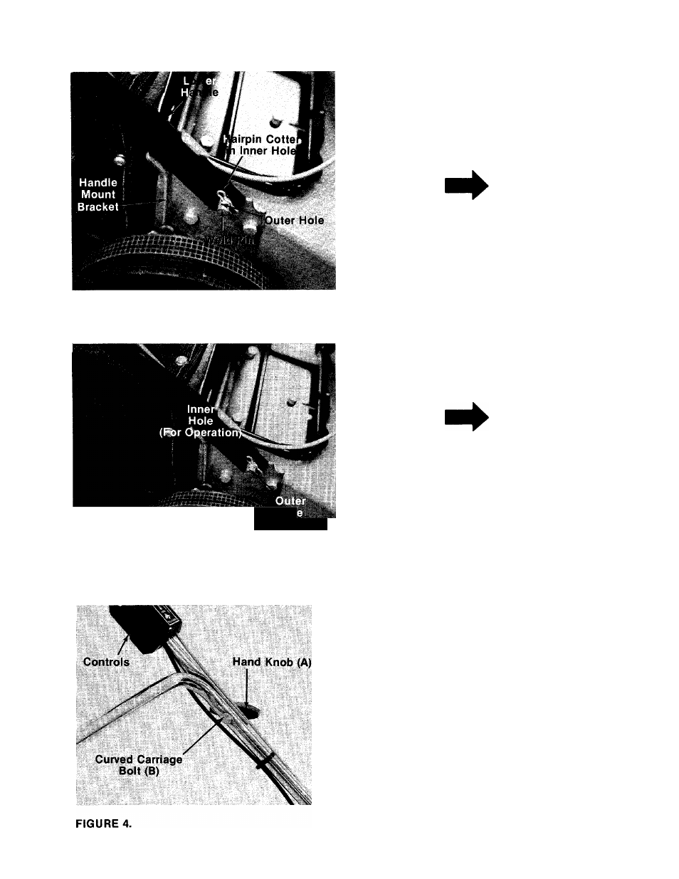
NOTE
There are two (2) holes in the handle
■ mount brackets. Place hairpin cot
ter in the inner hole for operation.
The outer hole is for storage. See
figure 3.
FIGURE 3.
4. Place upper handle in position over lower han
dle. Controls should be on the left side of the
handle. Blade brake/clutch control wire must
be assembled so that it is behind the handle
as shown in figure 4.
Secure with two carriage bolts (B) and hand
■knobs (A) as shown in figure 4. The knobs can
be either to the inside or outside of the han
dle.
NOTE
Reference to left or right side of
machine is determined from oper
ator’s position at the handle facing
forward.