Connecting doorlocks, Type c" reverse polarity (5-pin harness), Installation diagram – Bulldog Security 22I User Manual
Page 9: Connecting door locks -17, I/i 4
Attention! The text in this document has been recognized automatically. To view the original document, you can use the "Original mode".
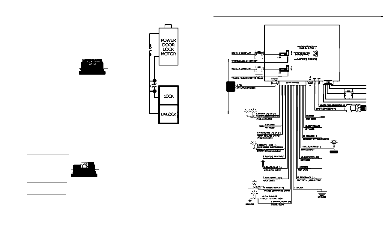
CONNECTING DOORLOCKS
i/i 4
U)
< 3
& 1
a
in ^
'Type C" Reverse Polarity
(5-pin harness)
GREEN/BLACK Unlock Out
GREEN/WHITE Unlock In
CUT
HERf •
RED/BLACK
•f 12V Constant
BLUE/BLACK Lock Out
BLUE/WHITE Lock In
CUT
HERE'
NOTE: Connect the RED WITH BLACK STRIPE
wire to + 12V constant power.
U)
(/>
<
Q.
in
One Wire Door Lock System (This is an example only)
GREEN/BLACK Lock Out
GREEN/WHITE Not Used
RED/BLACK
BLUE/BLACK Lock Out
—vw----------
620 OHM resistor
to unlock, must
be 5% tolerance.
■I-12V Constant
-------wv---------
2700 OHM resistor
to lock, must be
S% tolerance.
NOTE: Connect the RED WITH BLACK STRIPE
wire to +12V constant power.
BLUE/WHITE Not Used
This is an example
only. Resistor values
and 12V or ground
may
vary depending
on make and model
of the vehicle.
16
02003 Aaest 2 CcmmuniOHlonv ktc
INSTALLATION DIAGRAM
Kutwrwt
itiiMiMm
02003
3 CoRwnuniutwov Inc.