Connecting the 18-pin harness, Connecting doorlocks, Ii) hi e) iii 0 d] dl 0 – Bulldog Security 22I User Manual
Page 10
Attention! The text in this document has been recognized automatically. To view the original document, you can use the "Original mode".
CONNECTING THE 18-PIN HARNESS
MODULE LAYOUT
l$-P]NHAftN€SS
ANTENNA
® II) HI E) III 0 d] dl 0
000« LOCK HARNESS
(GN 1 IGN 2
ai ¿3QQ II
7®^
□ BBS
IN(+)
g
OUT(-)
PARKING LIGHT TRUNK DOME LIGHT
CAUTION: Please check the position of the switch before the wire connection is made.
You may cause damage to the control module if the incorrect switch polarity is chosen.
1. BROWN (+) or (-) Parking Light Output
5.
8.
9.
Attach to the vehicles parking light wire.
Note: Adjust the switch for
positive or negative output.
ORANGE Not Used
WHITE/RED (+) or (-) Trunk Release or Channel #2 Output
Note: Adjust the switch for positive or negative output.
VIOLET (-»■) or (•) Dome Light Output
Provides positive or negative output for domelight supervision.
Note: Adjust the switch for positive or negative output.
BLUE (-) AMA (Aftermarket Alarm Activation)
When this wire receives a ground signal, it can start or stop the remote
starter section of the unit.
BLACK/BLUE (-) Negative Trip Input Wire
For hood pin switch or aftermarket sensors.
BLACK/WHITE (-) Tach (Optional)
MUST USE WITH DIESEL ENGINES
Attach to the negative side of the coil or coil pack.
Note: You must
program for tach and tach learn when using this wire.
(See Programming Tach/Tachtess and Diesel Start, page 21.)
GREEN/BLACK (+) Diesel Glow Plug Input (Optional)
This wire is for diesel vehicles with a positive glow plug light wire to
delay the remote starter. You may also program module for time start
delay.
(See Programming Glow Plug Timer, page 22.)
BROWN/BLACK (-) Diesel Glow Light Input (Optional)
This wire is for vehicles with a negative glow plug light wire to delay the
remote
starter.
You
may
also
program
your
module
for
time
delay
start.
(See Programming Glow Plug Timer, page 22.)
10. Open Pin Not Used
lO
02003 Accns 2 Communications hic
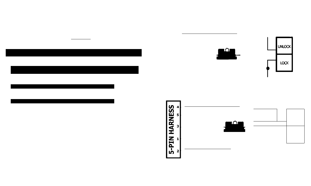
CONNECTING DOORLOCKS
OC
< 3
z
5^
Q.
in
"Type A" (+) Positive (5-pin harness)
GREEN/BLACK Unlock Out____________
I
GREEN/WHITE Not Used
RED/BLACK
+12V Constant
BLUE/BLACK Lock Out
BLUE/WHITE Not Used
NOTE: Connect the RED WITH
BLACK STRIPE wire to +12V constant.
"Type B" (-) Negative (5-pin harness)
GREEN/BLACK Unlock Out
i
GREEN/WHITE Not Used
RED/BLACK
BLUE/BLACK Lock Out
BLUE/WHITE Not Used
NOTE:
Connect
the
RED
WITH
BLACK STRIPE wire to ground.
UNLOCK
Ground
j__________
LOCK
15
02003 Ac(«t 2 ConvnufKMions Inc