Figure 7 - drip leg location, Pilot – Bryant 452W User Manual
Page 6
Attention! The text in this document has been recognized automatically. To view the original document, you can use the "Original mode".
DRIP LEG
WITHIN STRUCTURE
A70676
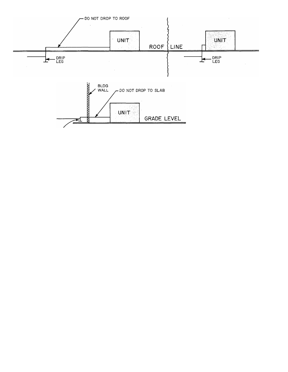
Figure 7 - Drip Leg Location
on the right side. Install a drip leg trap in the gas sup
ply riser leading to the unit.
The following are pertinent recommendations:
1. Avoid low spots in long runs of horizontal pipe. It
is best to grade all pipe 1/4 inch for every 15 feet
to prevent traps. All horizontal runs should grade
downward to risers. Use risers to connect to unit
and to meter.
2. Install drip leg in riser leading to unit. Drip leg
will serve as trap for dirt and condensate. Install
drip legs where condensate will not freeze. See
Figure 7 for drip leg location.
3. Install wrench-type shutoff valve in gas supply
line within sight of, and convenient to, unit.
4. Place ground joint union close to unit between
gas controls manifold and wrench-type shutoff
valve.
5. Support all piping with appropriate hangers.
Maximum distance between hangers should be
10 feet.
6. Joint compound (pipe dope) which is resistant to
action of liquefied petroleum gases should be ap
plied sparingly and only to male threads of
joints.
7. After all gas pipe connections are made, purge
lines and check for leakage. Turn off power sup
ply to unit when purging lines to prevent glow
coil in reignition pilot from being energized. Use
a soap-and-water solution for leak-checking.
WARNING:
Never
use
maiclies.
candles,
or
other
.sources ol' ignition to check for gas leakage.
Pilot
Both natural gas and propane gas units are equipped
with an automatic reignition pilot. The pilot will light
automatically when supplied with gas and is elec
trically energized.
Light the pilot using the procedure outlined on the
lighting instruction plate attached to the generator.
However, when lighting the pilot for the first time,
perform the following additional steps:
1. If supply line was not purged prior to connecting
unit, it will be full of air. Because venting air
through small pilot port is a lengthy process, it is
recommended that pilot supply line be discon
nected at pilot shutoff valve and supply line be
allowed to purge until odor of gas is detected.
WARNING: Never purge gas lines inii) the com
bustion chamber.
Immediately upon detection of gas odor, recon
nect pilot supply tube. Allow 5 minutes to elapse
and light pilot in accordance with instructions on
lighting plate.
2. Pilot flame should be soft blue in color and of
sufficient length to provide good impingement on
unimetal of Bryant pilot. Flame should, extend
upward between carryover ports of two adjacent
burners.
3. If pilot flame does not have appearance
described above, adjust it by means of manual
pilot shutoff valve.
a. The valve is equipped with an adjustable
screw. Turn handle to full open position, and
— 6