E. water coil connections, Table ii, Iii. making electrical connections – Bryant 452W User Manual
Page 5: Iv. making gas connections
Attention! The text in this document has been recognized automatically. To view the original document, you can use the "Original mode".
E. Water Coil Connections
1. If cooling coil is used in connection with heating
unit, and heating unit is not approved for in
stallation downstream from cooling coil, install
cooling coil in parallel with, or downstream of,
heating unit. This will avoid condensation in
heating unit. If coil and heating unit are in
stalled in parallel, dampers or other means used
to control flow of air should be adequate to
prevent chilled air from entering heating unit,
and if manually operated, shall be equipped with
means to prevent operating of either unit unless
dampers are in full heat or cool positions.
2. If coil is located in warm air stream, do not con
nect polyethylene pipe directly to coil. Connect
minimum of 24 inches of copper or galvanized
pipe to both coil inlet and outlet. Then connect
plastic pipe to these nipples.
3. Precautions must be taken to provide for water
expansion on installations where outside piping
is subject to freezing temperatures and coil is in a
heated air stream. The connecting polyethylene
plastic pipe acts as an expansion vessel if there is
enough footage of this pipe in heated space
(space not subject to freezing temperatures).
Table II shows minimum lengths (total inlet and
outlet) of plastic piping of various diameters
required to provide adequate expansion volume.
If total plastic chilled-water line footage in heated
space is not as long as minimum value shown in Table
II, tee off additional length of polyethylene pipe to
either side of coil to meet required footage. Cap open
end of added polyethylene pipe.
TABLE II
Nominal Pipe Size
(Inches)
Length of Plastic Pipe
(Feet)
1
60
1-1/4
35
1-1/2
25
III. MAKING ELECTRICAL CONNECTIONS
1. Make all electrical connections in accordance
with the National Electrical Code and any local
ordinances or codes that might apply.
2. The unit must be electrically grounded in ac
cordance with the National Electrical Code,
ANSI Cl dated 1968 when installed.
3. Provide separate power supply for air con
ditioner.
4. Provide fused disconnect switch within sight of,
and not more than 50 feet from, absorption unit.
Use 35-amp standard fuse or 25-amp fusetron.
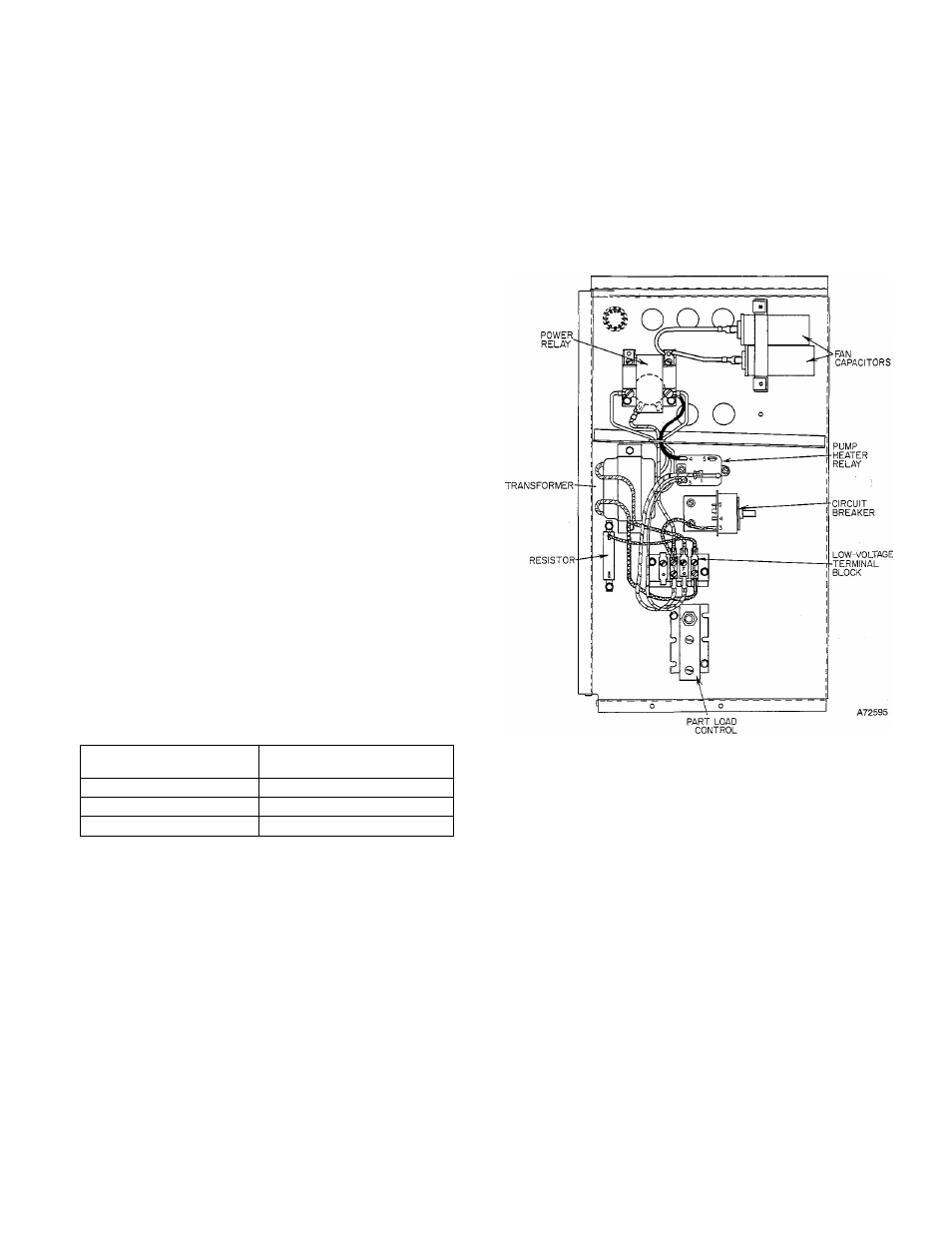
5. Unit ■ is shipped from the factory completely
wired. Connection of the power supply to power
relay is made directly into control box through
knockout in corner panel on right side of unit.
Low-voltage (24-V) wires from thermostat con
trol enter directly into control box through
knockout in panel on right side. Low-voltage
wires are connected at terminal block. See Figure
6 for location of control box components.
6. Figm-e 9 is a line-to-line wiring diagram of unit.
7. Disconnect chilled-water pump electrical leads
at power relay in control box before energizing
unit when ready to check field wiring. Do not
operate pump dry.
Figure 6 - Control Box Components
IV. MAKING GAS CONNECTIONS
Consult local gas company before making any gas
connections. In case of conflict with this instruction,
local requirements should be followed. This appliance
is not suitable for use with conventional venting
systems.
Refer to the American National Standard for In
stallation of Gas Appliances and Gas Piping Z21.30
dated 1964, in the absence of local building codes.
Before selecting the size and type of pipe that is to be
used for installing the absorption unit, be sure to
check with local gas company for the necessary in
formation. The size of the gas pipe to be. used between
meter and unit will depend upon the length of run
and the allowable pressure loss established by the
utility.
The gas connection to the unit is made to the 3/4-inch
shutoff valve at the control manifold. The supply pipe
enters the unit through an opening in the corner panel
— 5