Sections: controls, Ignition switch, Throttle control – Bolens LT-185 User Manual
Page 11: Choke control, Light switch, Ammeter, Hydrostatic control lever, Clutch-brake pedal
Attention! The text in this document has been recognized automatically. To view the original document, you can use the "Original mode".
4,
5.
6
.
Attach the positive (red) cable to the positive
terminal of the battery. Secure with hex bolt and
nut previously removed. Slide rubber boot down
over the positive terminal.
Remove the hex bolt and nut from the negative
(black) cable. Attach negative cable to the
negative terminal with this bolt and nut.
Secure battery by hooking battery strap into slot
7.
8
.
in rear frame, under the fender. See Figure 9.
Insert the drain tube through the hole in the
transaxle reinforcement bracket located on the
right side of the unit. See Figure 9. Be certain
drain tube is routed away from the wheel rim.
Trim excess end of drain tube if necessary
(about 4" should extend past the bracket or
cable tie).
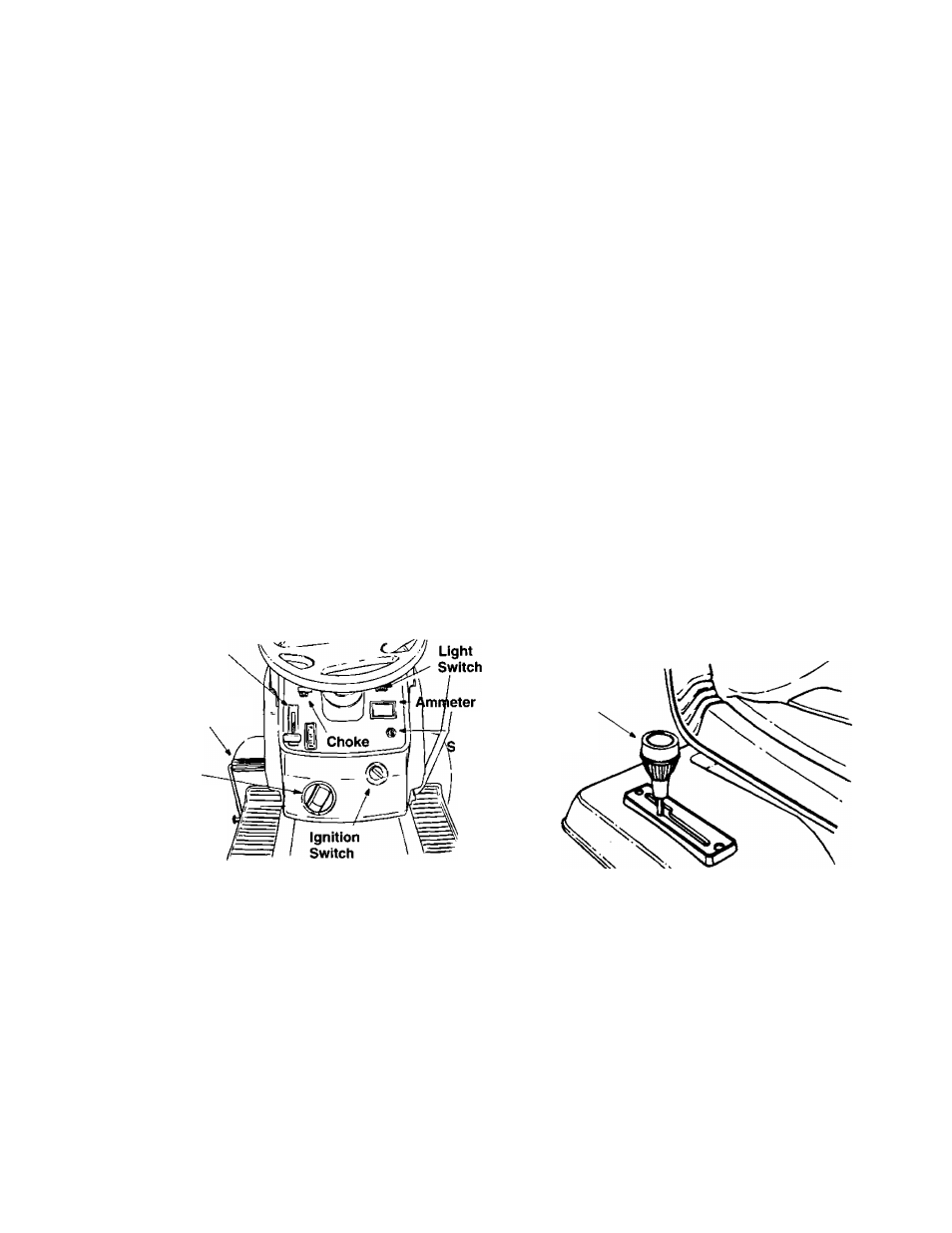
SECTIONS: CONTROLS
IGNITION SWITCH
The ignition switch is located on the dashboard. Turn
the key to the START position to start the engine.
When the engine is running, leave the key in the ON
position. To stop the engine, turn the key to the OFF
position. See Figure 10.
A
WARNING:
Remove key from the
tractor when tractor is not in use to prevent
accidental starting.
THROTTLE CONTROL
The throttle control is located on the dashboard and
is used to regulate the engine speed. To get
maximum efficiency from cutting, the throttle should
be in the FAST position when operating the mower.
See Figure 10.
Throttle
Control
Clutch-Brake
Pedal
Deck
Height
Adjustment
Knob
PTO
witch
Figure 10
CHOKE CONTROL
The choke control is located on the left side of the
dashboard and is operated manually. Details for the
choke operation are covered in the separate engine
manual packed with your unit. See Figure 10.
LIGHT SWITCH
The head tamps are operated by pushing the light
switch located on the dashboard. The head lamps
will only operate when the engine is running. See
Figure 10.
AMMETER
The ammeter registers the rate of battery charge or
discharge. The ammeter will register on the discharg
ing side with starting the engine. It should register on
the opposite side (charging) when the engine is run
ning in the fast position until the battery is completely
charged. With a fully charged battery or with the
engine idling, the ammeter will not show a charge.
See Figure 10.
HYDROSTATIC CONTROL LEVER
The hydrostatic control lever is located on top of the
fender on the right side of the tractor. This single con
trol lever, connected to the hydrostatic transmission,
controls both the speed and direction of the tractor.
Infinite speed control is achieved by moving the con
trol lever forward or backward. The farther forward or
backward you move the control lever, the faster you
will travel. Pulling the control lever into neutral (N)
area will stop the tractor. See Figure 11.
Hydrostatic
Control
Lever
Figure 11
CLUTCH-BRAKE PEDAL
The clutch-brake pedal is located on the left side of
the tractor. See Figure 10. Depressing the pedal
returns the drive unit to neutral (N) and applies the
brake.
NOTE:
The clutch-brake pedal must be depressed
to start the engine.
11