Sections: controls, Ignition switch, Throttle control – Bolens 820 thru 829 User Manual
Page 15: Choke control, Ignition/light switch, Ammeter (optional)
Attention! The text in this document has been recognized automatically. To view the original document, you can use the "Original mode".
/
Down
Rod
Figure 17
5.
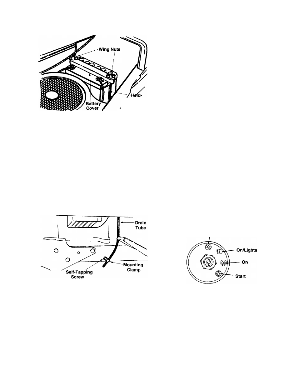
Route the battery drain tube over to the left side
of the tractor. Loosen the self-tapping screw
which secures the mounting clamp. See Figure
18. Slip the end of the drain tube into the
mounting clamp. Tighten the self-tapping screw
to secure the clamp. Do not overtighten which
could collapse the drain tube.
NOTE:
The vented battery allows any gases or
liquid from the battery to be drained onto the ground.
6.
Trim end of drain tube if more than 1 inch
extends below the frame.
Figure 18
SECTIONS: CONTROLS
IGNITION SWITCH
The ignition switch is located on the dashboard. The
engine is started by turning the key to the START
position. When the engine is running, leave the key
in the ON position. To stop the engine, turn the key
to the OFF position. See Figure 19 and 20.
dk
WARNING:
Remove the key from the
tractor when the tractor is not in use to
prevent accidental starting.
THROTTLE CONTROL
The throttle control is located on the left side of the
dashboard and is used to regulate the engine speed.
See Figure 20. The engine should be operated at full
throttle (FAST) when operating any equipment that
uses the tractor engine as a source of power such as
the mowing deck, snow thrower or rotary tiller.
CHOKE CONTROL
The choke control is located on the dashboard and
is operated manually. Details for the choke operation
are covered in the separate engine manual packed
with your unit. See Figure 20.
IGNITION/LIGHT SWITCH
To
prevent
accidental
starting
and/or
battery
discharge, remove the key from the ignition switch
when the tractor is not in use.
To start engine insert key into ignition switch and
turn clockwise to the START position. Release key
to the ON position once engine has fired. The lights
are controlled by the ignition switch. After the tractor
is running, turn the key counterclockwise to the
LIGHTS ON position. See Figure 19.
dk
WARNING:
To
prevent
accidental
starting and/or battery discharge, remove
the key from the ignition switch when the
tractor is not in use.
Off
Figure 19
AMMETER (Optional)
The ammeter registers the rate of battery charge or
discharge.
The
ammeter will register on the
discharging side when starting the engine. It should
register on the opposite side (charging) when the
engine is running in the fast position until the battery
is completely charged. With a fully charged battery
or with the engine idling, the ammeter will not show
a charge. See Figure 20.
15