Attaching the deck links (hardware a), Attaching the cutting deck (hardware b) – Bolens 820 thru 829 User Manual
Page 11
Attention! The text in this document has been recognized automatically. To view the original document, you can use the "Original mode".
Setting for
Left Rear Link
Hex
I
Nut
6 o
Eyeboit
y
“
\
Setting for
Front Links
Figure 7
Hex Boits
ATTACHING THE DECK LINKS
(Hardware A)
The three adjustable deck links have been shipped
unassembled. Attach as follows.
1.
Start 1/2" hex nuts on eyebolts until nuts are
flushed with ends of eyebolts. See Figure 7.
2.
Insert eyebolts and hex nuts into the adjustable
lift links located under the tractor. See Figure 7.
3.
Thread eyebolts into the lift links and hex nuts.
The left rear link should be adjusted so the
eyebolt hangs about 3-1/2 inches below the lift
link. The two front links should be adjusted so
the eyebolts hang about 2-1/8 inches below the
lift links. See Figure 7.
ATTACHING THE CUTTING DECK
(Hardware B)
NOTE:
The assistance of another person is helpful
when attaching the cutting deck.
1.
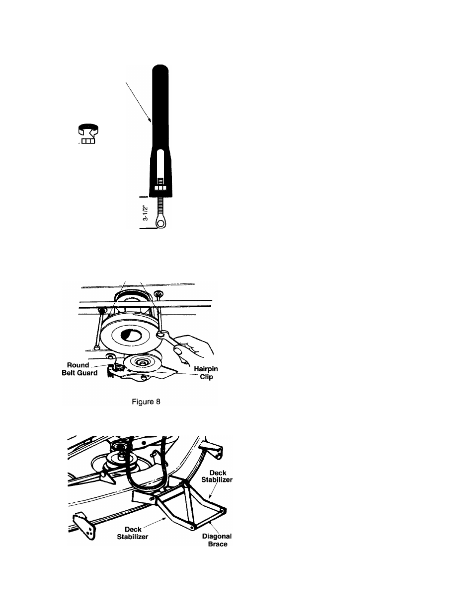
Working beneath the tractor, remove the round
belt guard from the idler by removing the hairpin
clip. See Figure 8. Remove the two hex bolts
which act as belt keepers by the engine pulley.
2.
Move the tractor lift handle all the way back to
the full raised position. Turn the tractor steering
wheel all the way to the right.
3.
Units with 50" Decks: Remove the roller
assembly from the rear of the deck and set
aside.
4.
The two deck stabilizers and the diagonal brace
which are attached to the front of the deck are
folded back over the deck for shipping purposes.
Unfold them at this time. See Figure 9.
5.
Slide the deck under the tractor from the left
side. You may need to angle the deck slightly to
get the braces past the front wheel.
NOTE:
When attaching the cross bar, reference to
the right or left hand side is observed facing the front
of the tractor.
6.
Standing in front of tractor, remove the hairpin
clips from the cross bar.
7.
Slide the cross bar to the left until the right side
is free. Drop bar down and slide to the right until
cross bar is removed from the tractor.
8.
Insert cross bar through the two deck stabilizers
and the diagonal brace. See Figure 10A.
Figure 9
11