Ad604, Ib ^ il j – Analog Devices AD604 User Manual
Page 22
Attention! The text in this document has been recognized automatically. To view the original document, you can use the "Original mode".
AD604
MEDICAL ULTRASOUND TGC DRIVING THE
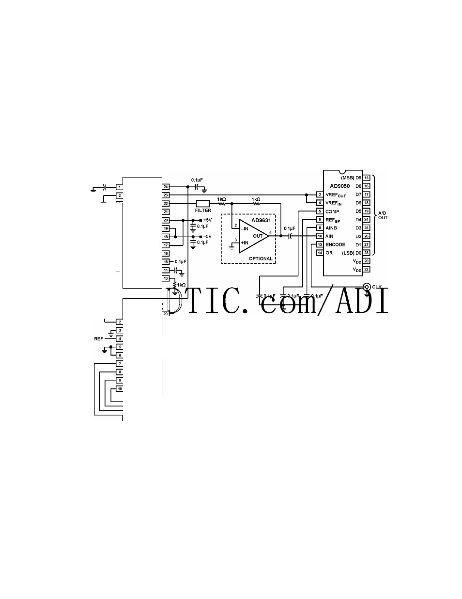
AD9050, A 10-BIT, 40 MSPS ADC
The AD604 is an ideal candidate for the time gain control (TGC)
amplifier that is required in medical ultrasound systems to limit
the dynamic range of the signal that is presented to the ADC.
Figure 52 shows a schematic of an AD604 driving an
in a typical medical ultrasound application.
The gain is controlled by means of a digital byte that is input to
an DAC that outputs the analog gain control signal.
The output common-mode voltage of the AD604 is set to VPOS/2
by means of an internal voltage divider. The VOCM pin is
bypassed with a 0.1 pF capacitor to ground.
The DSX output is optionally filtered and then buffered by
an
op amp output is ac-coupled into the self-biasing input of an
ADC that is capable of outputting 10 bits at a 40 MSPS
sampling rate.
0.1MF
0.1MF
ANALOG
INPUT
500
-w.-----
O.iMFij::
—
-------- Mi
0.1
m
F
------ ----------
-DSXI
VGN1
+DSX1
vref
PAO1
OUT1
FBK1
GND1
PAII
VPOS
COMI
VNEG
COM2
VNEG
PAI2
VPOS
FBK2
GND2
PAO2
OUT2
+DSX2
VOCM
-DSX2
VGN2
AD6O4
_ 1Oo
0 ]
v
out
B
VoutA
IB
^ il J
V
OuT
C
VoutD
V
DD
.. AD7226
Vref
AO
AGND
A1
DGND
WR
DB7
DB0
(MSB)
(LSB)
DB6
DB1
DB5
DB2
DB4
DB3
AO
17|—I
A1
l
e
T-l
WR 1
5
1-4
I------
DIGITAL GAIN CONTROL
Figure 52. TGC Circuit for Medical Ultrasound Application
Rev. E | Page 22 of 32
J2
5O0
19
+15V
11