Assembly, Instructions, Assembly instructions – Bolens 112-340A User Manual
Page 4
Attention! The text in this document has been recognized automatically. To view the original document, you can use the "Original mode".
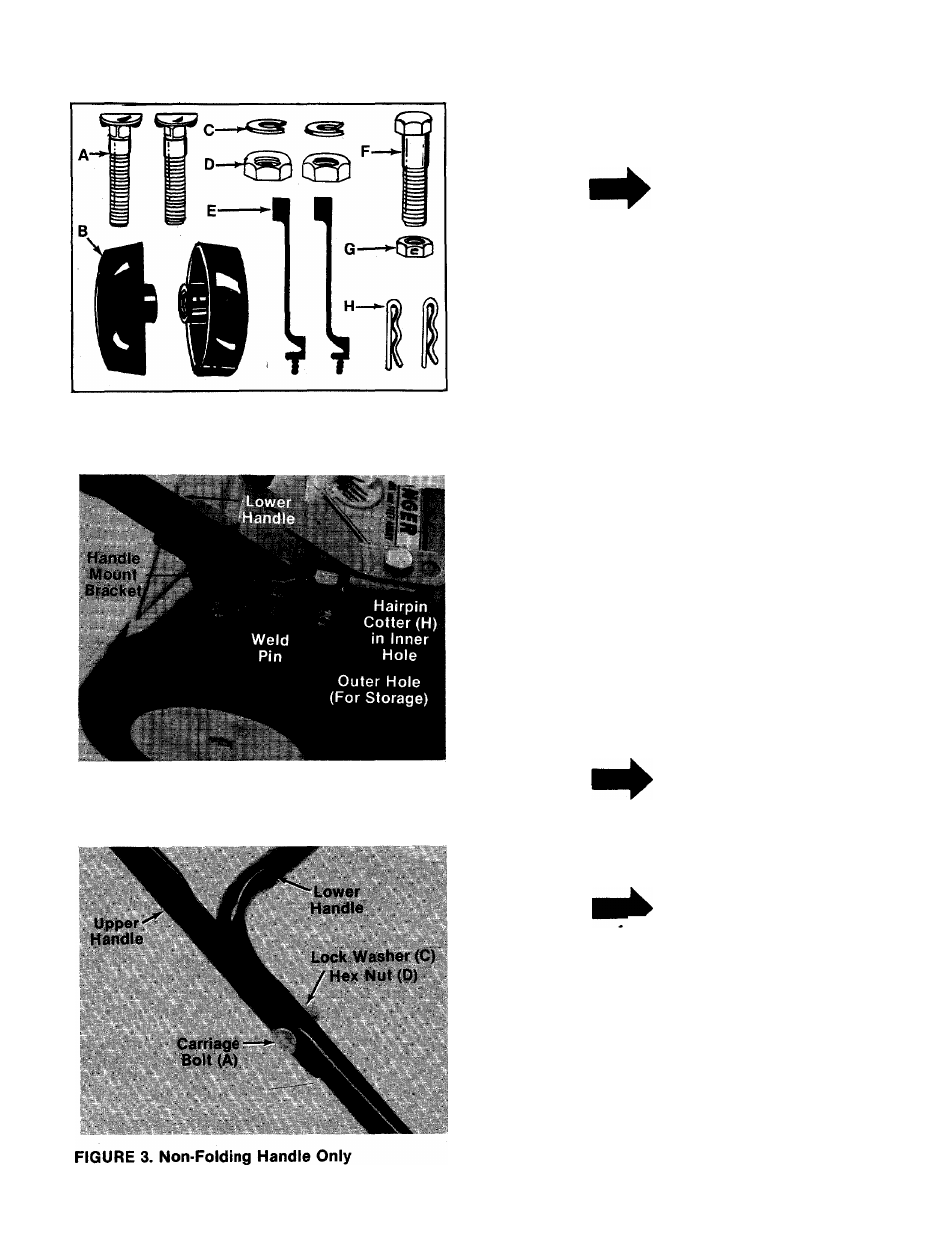
FIGURE 1.
FIGURE 2.
ASSEMBLY
INSTRUCTIONS
NOTE
This unit is shipped WITHOUT GAS
OLINE or OIL. After assembly, see
operating section of this manual for
proper fuel and engine oil recom
mendations.
1. Remove lawn mower and loose parts from car
ton. Make certain ail parts and literature have
been removed from the carton before the car
ton is discarded.
2.
Extend throttle control which is attached to
the engine at the rear of the mower and place
on the floor. Be careful not to bend or kink
control wire.
Contents of hardware pack: (See Figure 1)
(
2
)
D (2)
(
1
)
(
1
)
Curved Head Carriage Bolts
(2) Hand Knobs (Folding Handle Only)
(2) Lock Washers 5/16" I.D. (Non-Folding
Handle Only)
Hex Nuts 5/16-18 Thread (Non-Folding
Handle Only)
(2) Cable Ties
Hex Bolt V4-20
X
1.50" Long
Hex Lock Nut V4-20 Thread
H (2) Hairpin Cotters
3.
Fasten lower handle in position over weld
pins
in
handle
mount
brackets
on
deck.
Secure with hairpin cotters (H) in inner hole
on weld pin. See figure 2.
NOTE
There are two (2) holes in the handle
mount brackets. Place the hairpin
cotter in the inner hole for operation.
Outer hole is for storage.
NOTE
It may be necessary to bend the
ends of the lower handle inward
slightly to obtain a tight fit against
the handle mount brackets.
There are two height positions for the handle.
Place upper handle in position over lower han
dle, selecting hole for either high or low posi
tion. Refer to figure 14.
-A. Units with Non-Folding Handle—Secure
upper handle with two curved carriage bolts
(A), lock washers (C) and hex nuts (D). See
figure 3.