Bryant Model 516 User Manual
Page 3
Attention! The text in this document has been recognized automatically. To view the original document, you can use the "Original mode".
Limitations and Recommendations
1. The duct heaters should never be installed
from the bottom or the top of the duct - only
from the sides of the duct. The heaters must
always be installed on the discharge side of
the Fan Coil.
2. Only one duct heater may be used in any
one duct. If the capacity required exceeds the
output of one duct heater, select the total
number of heaters and proportion them in
separate runouts or separate ducts from the
plenum.
3. Install the duct heater at least 18 inches
away from any canvas duct connector. If the
heater must be located closer, replace the
canvas connector with an asbestos connector.
4 . The control enclosures of the duct heaters
must be completely accessible and so located
as to provide ventilation at all times.
5. The air duct should be installed in ac -
cordance with the standards of the National
Board of Fire Underwriters for the Instal
lation of Air Conditioning and Ventilating
Systems of other than Resident Type (pamphlet
no. 90A), and Resident-Type Warm Air Heat
ing and Air Conditioning Systems (pamphlet
no. 90B).
6. Each duct heater should be provided with
a fan relay. The heater and fan motor are to
be wired so that the duct heater cannot oper
ate unless the fan is on. Always hook the fan
interlock to the high-voltage side of the
system. Never use a fan delay with the
electric duct heater.
7.
The coil of the secondary contactor
(general-purpose, continuous duty rated at
6000 cycles) must be wired in series with the
manual reset limit control (TMR).
NOTE; Observe at least one complete heating
cycle before leaving the installation.
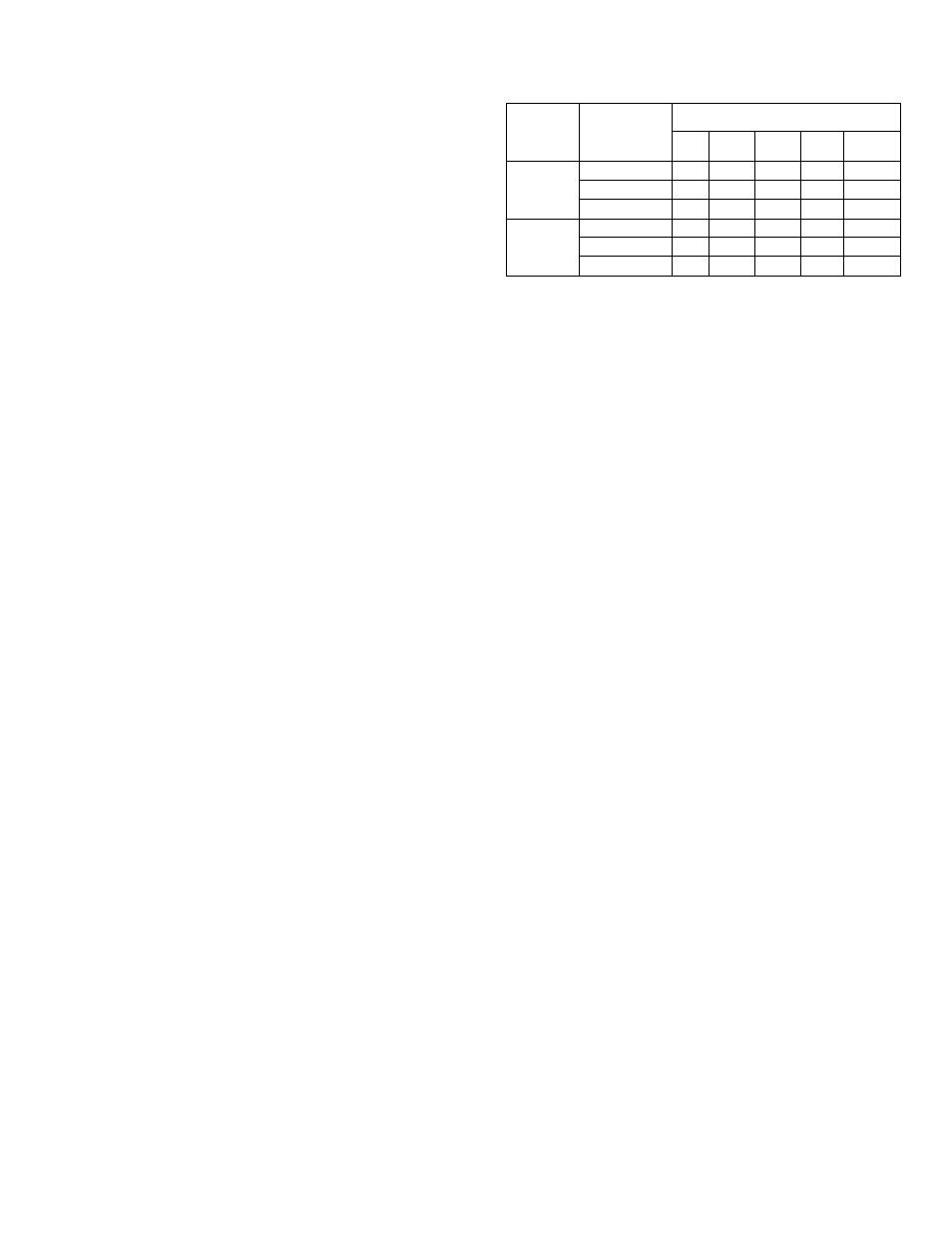
Table II - Air Delivery at Indicated Static Pressure
(Dry Coil, Less Filter)
Model
Evaporator
Motor
Speed Tap
CFM
*0.0
*0.1
*0.2
*0.3
*0.4
18-516
High
930
920
905
890
860
Medium
705
700
690
675
650
Low
605
600
590
580
550
24-516
High
955
940
915
880
830
Medium
695
690
680
670
680
Low
615
605
600
580
555
* Static pressure - inches w.c.
Electrical Connections
Make all electrical connections in accordance
with the National Electric Code and any local
codes or ordinances that may apply.
Provide power supply (or supplies; 11- throu^
14.4-KW heaters will have two power sup
plies) for the heating capacity of the unit
being installed in accordance with Table I -
Ratings and Capacities. Power supply con
nections are made at the high-voltage termi
nals with wire suitable for at least 90° C
(194°F). It is good practice to ground casing
parts and to check factory wiring connections,
to be sure none were loosened in transit or
installation. Refer to Figures 5, 6, and 7 for
field wiring diagrams.
Thermostat Connection
The electric duct heater and Model 516 Fan
Coil Unit are designed for use with a 24-V
heat-cool thermostat, Bryant Model 883 .
Connect the thermostat and the low-voltage
terminal block on the side of the Fan Coil in
accordance with field wiring diagrams -
Figures 5,
6, and 7. Set the thermostat
heating anticipator at 0.8 amps .
- 3 -
39516D3