Figure 15, Note, Important – Bolens 113-084A User Manual
Page 11
Attention! The text in this document has been recognized automatically. To view the original document, you can use the "Original mode".
5. Disconnect the “Z” fitting on the blade
brake/clutch cable from the clutch control
handle. Slide the blade brake/clutch cable out
of the control housing.
6. Disconnect the throttle control cable from the
engine by loosening screw on engine and
disconnecting the “Z” fitting. See figure 15.
“Z
Thro
Fitting on Screw on ^
tie Control
Engine
-able
_
FIGURE 15.
7. Tip the mower on its side. Remove the blade
by removing two hex nuts and lock washers.
Refer to figure 13.
NOTE
When reassembling, tighten hex
nuts to between 350 and 600 in. lbs.
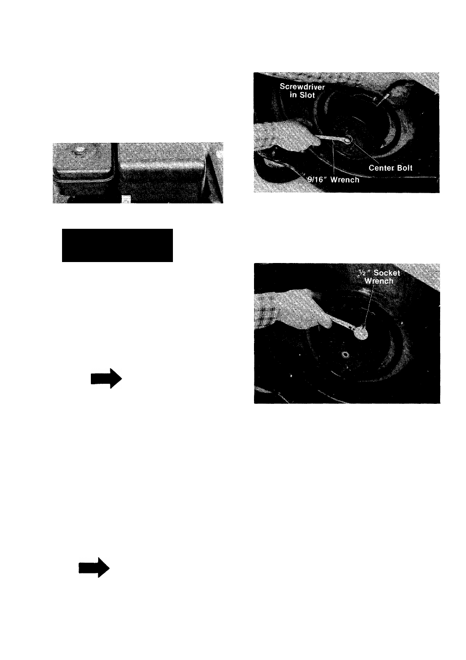
8. Remove the center bolt as follows.
a. Insert a screwdriver into the slot provided
in the blade brake/clutch housing where
the control cable enters housing. See
figure 16.
b. Place a 9/16" wrench on the center bolt.
Turn the wrench slowly until the screw
driver catches in a groove provided inside
the clutch. The screwdriver will now keep
the clutch from turning, and the center bolt
and two belleville washers may be re
moved.
IMPORTANT
Upon reassembly, be certain to
tighten center bolt to between 350
and 600 in. lbs.
FIGURE 16.
9. Support the engine with one hand. Remove
the three self-tapping screws which secure
the deck and blade brake/clutch to the engine.
A V
2
" socket wrench is required. See figure
17.
FIGURE 17.
10. Slide the blade brake/clutch cable through the
hole in the deck as you lift off the engine and
blade brake/clutch. Be careful not to kink con
trol cable.
11. Remove blade brake/clutch from engine
crankshaft.
Blade Brake/Clutch Installation
1. Place the new blade brake/clutch on engine
crankshaft.
Line
up
holes
on
blade
brake/clutch with mounting holes on engine.
2.
Place the two belleville washers onto
crankshaft. Cupped side of washers must be
against the blade brake/clutch. Secure with
hex bolt finger tight only.
3. Place cable through engine mounting hole on
deck.
4. Reverse steps 1 through 10 of preceding sec
tion for reassembly.
11