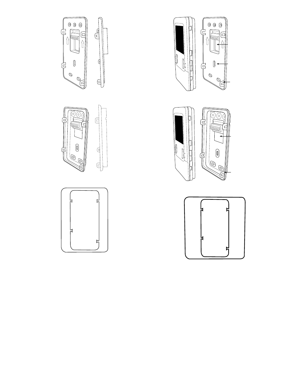
Fig. 3—recessed mount backplate, Fig. 4—surface mount backplate, Fig. 5—thin decorative backplate – Carrier Infinity SYSTXCCUID01 User Manual
Page 3: Fig. 6—recessed mount assembly, Fig. 7—surface mount assembly, Fig. 8—large decorative backplate
c. Discard or recycle old thermostat.
NOTE:
Mercury is a hazardous waste and MUST be disposed of
properly.
3. Select Infinity Control™ mounting plastic (recess mount or
surface mount and decorative backplate if desired).
4. Route wires through large hole in mounting plastic. Level rear
plastic against wall (for aesthetic value only - Infinity Con-
trol™ need not be level to operate properly) and mark wall
through two mounting holes.
5. Drill two 3/16 inch mounting holes in wall where marked.
6. Secure mounting plastic to wall using two screws and anchors
provided.
7. Adjust length and routing of each wire to reach each wire
entry on the connector backplate. Strip ¼ inch of insulation
from each wire.
8. Match and connect thermostat wires to proper terminals on
User Interface backplate. See wiring diagram figures 12, 13
and 14.
A — Green = Data A
B — Yellow = Data B
C — White = 24VAC (Com)
D — Red = 24VAC (Hot)
NOTE:
It is not mandatory that the above color code be used, but
each ABCD connection in the system MUST be wired consis-
tently. A separate ABCD Connector comes inside packaging and
should be used when connecting to the furnace (or fan coil). (See
Fig. 10)
NOTE:
Insert connector properly into circuit board.
Fig. 3—Recessed Mount Backplate
A03186
Fig. 4—Surface Mount Backplate
A03187
Fig. 5—Thin Decorative Backplate
A04017
Fig. 6—Recessed Mount Assembly
A03190
Recessed terminal
block in wall 1
1
/
2
˝
wide by 2
1
/
8
˝ high
Recessed Mount
Interlocking Tabs (4)
Fig. 7—Surface Mount Assembly
A03191
Surface Mount
Backplate to wall
Interlocking Tabs (4)
Fig. 8—Large Decorative Backplate
A03188
3