Assembly instructions – MTD 111-070A User Manual
Page 8
Attention! The text in this document has been recognized automatically. To view the original document, you can use the "Original mode".
Inner
Hole
FIGURE 8.
ASSEMBLY
INSTRUCTIONS
(Loop Handle)
1. Extend throttle control which Is attached to
the engine at the rear of the mower and place
on the floor. Be careful not to bend or kink
control wire.
2. Fasten lower handle in position over weld
pins in handle mount brackets on deck.
Secure with hairpin cotters in inner hoie on
weld pin. See figure 8.
NOTE
There are two (2) holes in the handle
mount brackets. Place the lower
handle against the brackets and
secure with hairpin cotter in the in
ner hole. Inner hole is for operation.
Outer hole is for storage.
NOTE
It may be necessary to pull open the
ends of the lower handle. This will
insure a tight fit when assembled in
to handle mount brackets.
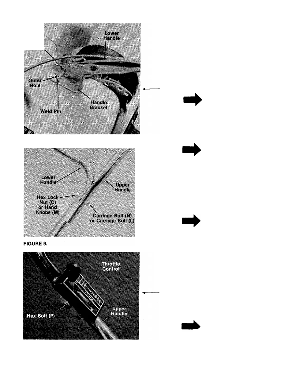
3. Assemble upper handle to lower handle.
Secure with two carriage bolts (L or N) and hex
lock nuts (O) or hand knobs (M) as shown in
— figure 9.
NOTE
There are two height positions for
the handle. See adjustment section.
4. Place the throttle control in position on right
side of upper handle. Secure with hex bolt (P)
and lock nut (Q). See figure 10.
FIGURE 10.
NOTE
Reference to right and left hand
sides of the unit is observed from
the operating position.