Assembly instructions – MTD 111-070A User Manual
Page 6
Attention! The text in this document has been recognized automatically. To view the original document, you can use the "Original mode".
ASSEMBLY
INSTRUCTIONS
(Hairpin (T) Handle)
NOTE
This
unit
is
shipped
WITHOUT
GASOLINE or OIL. After assembly,
see
operating
section
of
this
manual for proper fuel and engine
oil recommendations.
Your new mower is shipped preassembled with
the exception of the handie and wheeis.
1. Remove lawn mower and all parts from the
carton. Make certain that aii ioose parts and
iiterature have been removed before the car
ton is discarded.
NOTE
Throttle control may be optional
on your unit.
2. Extend throttle control assembly which is at
tached to engine at the rear of the mower and
place on floor.
A'
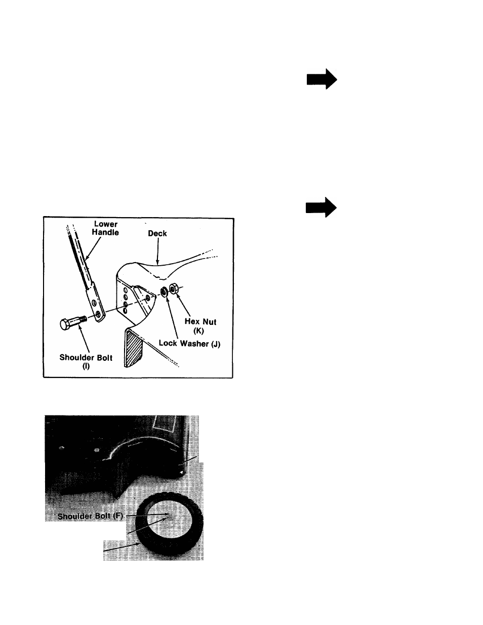
-3.
FIGURE 3.
CAUTION
Do not bend or kink controi wires.
Place lower handle in iine with hoie on deck.
Secure to deck with shoulder bolts (I), lock
washers (J) and hex nuts (K). See figure 3.
NOTE
It may be necessary to bend the
ends of the lower handle inward
siightly to assure a snug fit against
the deck mounting area.
Four
Cutting
Heights
Belleville Washer
Wheel
4. Your mower has four height settings. Use the
same hoie for ali four wheels when assem
bling. See figure 4.
5. Place shoulder bolt (F) through wheel. See
figure 4.
■6. Place crown side of beileville washer towards
the wheel (away from deck). See figure 4.
7. Secure wheei to deck, using hex nut (H) and
iock washer (G).
FIGURE 4.