Caution, Operation, Adjustments – MTD 111-070A User Manual
Page 10
Attention! The text in this document has been recognized automatically. To view the original document, you can use the "Original mode".
OPERATION
CAUTION
DO
NOT
OPERATE
M O W E R
U N L E S S
GUARD
OR
ENTIRE
GRASS CATCHER IS
IN ITS PROPER PLACE.
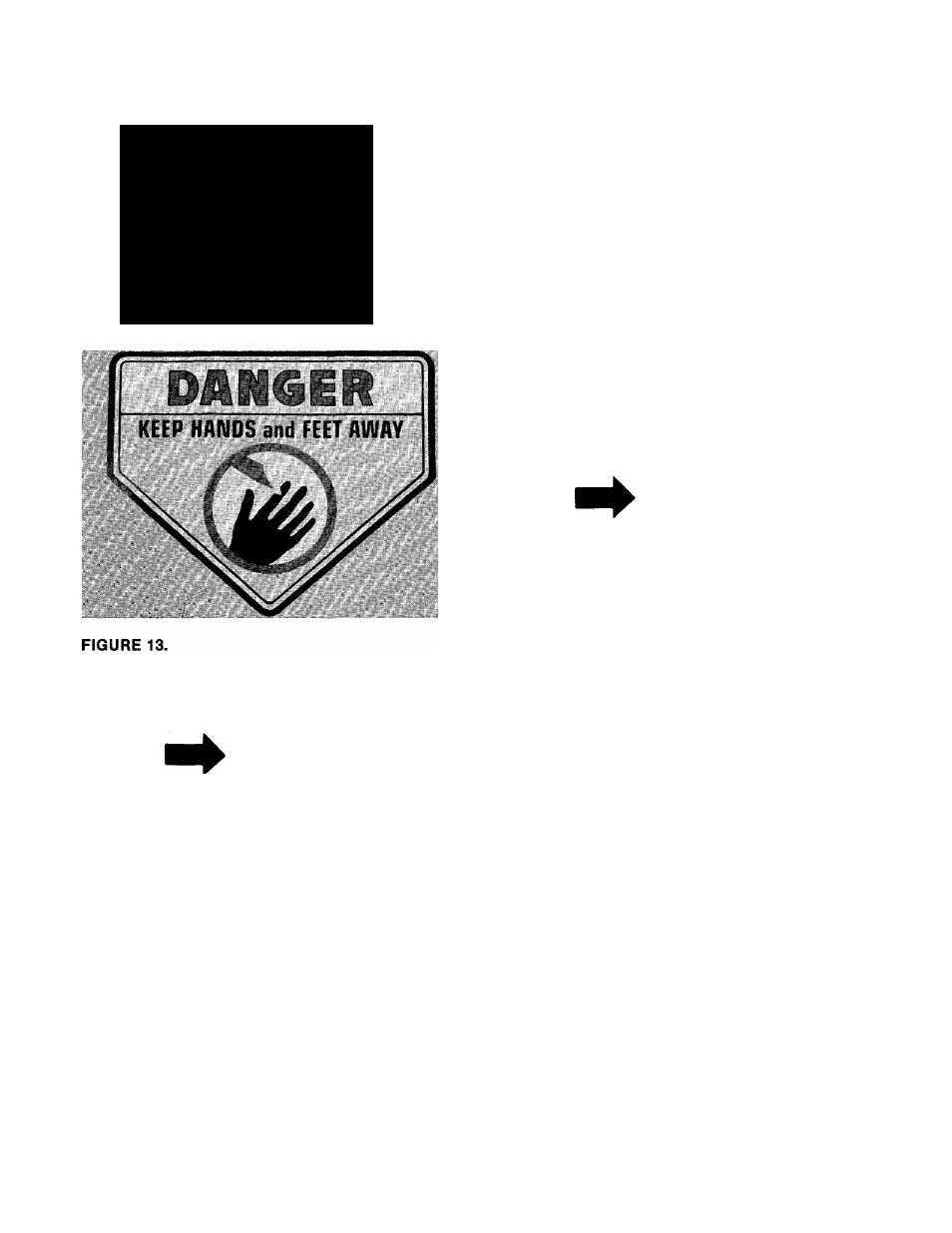
Keep hands and feet away from the chute area on
cutting deck. See figure 13.
NOTE
For shipping purposes your mower
is set with the wheels in a low cut
ting
height
position.
For
best
results raise the cutting position un
til it is determined which height is
best for your lawn. See adjustment
section.
1. FILL SUMP WITH OIL—Use a high quality
detergent oil classified “For Service SC, SD,
SE or MS”. Nothing should be added to the
recommended oil.
SUMMER
(Above 40° F.)
Use SAE 30
If not available,
Use SAE 10W-30
or
SAE 10W-40
WINTER
(Under 40° F.)
Use SAE 5W-20 or SAE 5W-30
If not available.
Use SAE low or SAE 10W-30
DIRECTIONS: Place the engine level. Remove oil
filler plug. FILL THE OIL SUMP TO POINT OF
OVERFLOW. Pour slowly. Capacity 1V4 pints.
2. FILL FUEL TANK—Use clean, fresh, regular
grade automotive gasoline. Fill tank com
pletely!
DO NOT MIX OIL WITH GASOLINE.
3. When ready to start engine, place throttle con
trol lever on handle in “START” position and
start engine in accordance with instructions
in engine manual. After engine starts, move
throttle control lever on handle to desired
engine speed. The engine is stopped by plac
ing control lever on handle in the “STOP”
position.
4. Be sure that lawn is clear of stones, sticks,
wire, or other objects which could damage
lawn mower or engine. For best results and to
insure more even grass distribution, do not
mow when lawn is excessively wet.
IMPORTANT
After striking a foreign object, stop
the engine. Remove wire from spark
piug, thoroughly inspect the mower
for any damage, and repair the
damage
before
restarting
and
operating the mower.
ADJUSTMENTS
A
CAUTION
Do not at any time make any adjust
ment to lawn mower without first
stopping engine and disconnecting
spark plug wire.
EASY CUTTING HEIGHT
An adjusting plate and thumb lever at each wheel
position provides cutting height adjustment. Each
adjusting plate has five holes. Height of cut will
be changed when the thumb lever, is moved from
one hole to another. Simply depress thumb lever
towards
wheel
and
move
wheel
and
lever
assembly to desired position. All wheels must be
placed in the same relative position.
CUTTING HEIGHT
Adjustment may be made by removing and moving
wheel studs to desired position. Cutting heights
will be raised as wheel studs are moved to a lower
hole and lowered as wheel studs are moved to a
higher hole in the deck. All wheel studs must be
mounted in a relative position to the deck. See
figure 4.
10