30" & 32" decks, 36", 38", 42" & 46" notch, Assembly of cover – MTD 190-063-000 User Manual
Page 5
Attention! The text in this document has been recognized automatically. To view the original document, you can use the "Original mode".
a.
b.
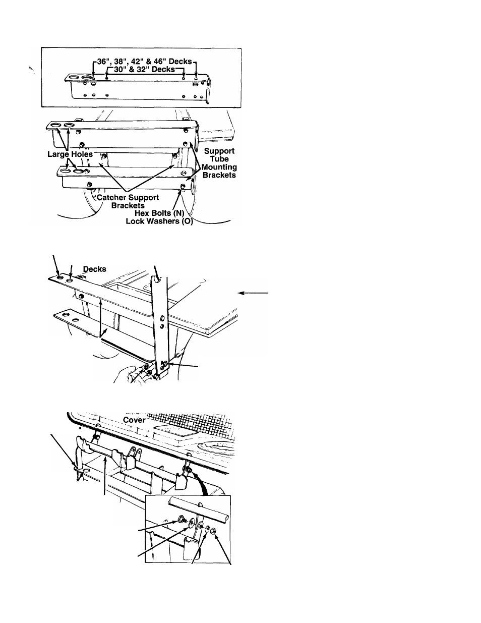
FIGURE 9.
Hex Nuts (P)
2. Attach the two support tube mounting brackets to
the support brackets as follows.
Examine the illustration in figure 9 to deter
mine which holes in the support tube mount
ing brackets to use for your unit.
Place the support tube mounting brackets in
position against the support brackets. See fig
ure 9. The large holes in the support tube
mounting brackets go to the left side of the
unit. The flange in the brackets go toward the
top.
c. Secure with hex bolts (N), lock washers (O)
and hex nuts (P), finger tight only. After all
eight hex bolts and nuts are assembled, then
tighten securely.
NOTE: It may be necessary to spread the support
brackets slightly in order to align the holes.
30" & 32" Decks
36", 38", 42" & 46" Notch
Latch
Support
Bracket
Support Tube
Mounting
Brackets
Lock Washer
FIGURE 10.
Hex Bolt
(K)
^Hex Nut
(M)
30" & 32
36"
38", 42“ & 46'^
Support Tube
Assembly
Shoulder
Bolt (F)
Belleville
Washer (G)
FIGURE 11.
Lock Hex
Washer (H) Nut (I)
Assemble the latch support bracket to the right
side of the support tube mounting brackets using
the upper set of holes in the latch support brack
et as shown in figure 10. Assemble so the notch
in the top of the latch support bracket is toward
the rear of the unit. Secure with two hex bolts (K),
lock washers (L) and hex nuts (M).
ASSEMBLY OF COVER .
(Group B)
Place the support tube assembly in position on
the rear of unit by sliding the support tube down
through the holes in the left side of tube mounting
brackets. Use the inside hole for 36", 38", 42" and
46" decks. Use the outside hole for 30" and 32"
decks. See figures 10 and 11.
Place belleville washers (G) on shoulder bolts (F)
so that the crowned side of the washers is
against the head of the shoulder bolt.
Place the cover in position against the brackets
on the support tube assembly as shown in figure
11. (Allow the cover to rest on the seat of the
lawn tractor for ease of assembly.) Line up the
holes in the hinges of the cover with the holes in
the support tube.
Insert the shoulder bolts (with washers attached)
through the hinges on the cover and the support
tube assembly. Heads of the shoulder bolts go
toward the inside of the unit. Secure with lock
washers (H) and hex nuts (I). Do not overtighten.
Cover must be able to pivot on the support tube.
2
.
3.
4.