Assembly instructions, Assembly of grass catcher frame and bag, Hex sems nut (r) – MTD 190-063-000 User Manual
Page 3
Attention! The text in this document has been recognized automatically. To view the original document, you can use the "Original mode".
ASSEMBLY INSTRUCTIONS
N
A
WARNING: When mounting the 063 Grass Collector on a 600 series lawn tractor with a 36" or 38"
deck built prior to 1990, wheel weights must be installed for stability before the lawn tractor is
operated. Order part number 753-0476.
IMPORTANT:
For 600 series lawn tractors with a 38" “deep” deck (Model 805) produced prior to 1987, replace
the right hand blade on the deck with a 3” wide high lift blade (part number 742-0473A) for proper operation of the
Hex Bolt (S)
NOTE: Reference to right or left hand side of the unit
is observed from the driver’s seat, facing forward.
ASSEMBLY OF GRASS CATCHER FRAME AND BAG
(If Unassembled—Group D)
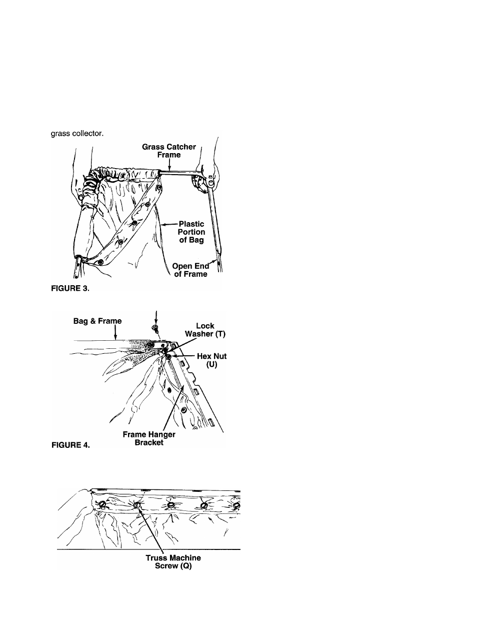
1. Feed frame into the channel on the fabric portion
----- of the grass catcher bag as shown in figure 3.
The plastic portion of bag goes toward the open
end of frame.
2. Attach one frame hanger bracket to the bag and
— frame as follows. See figure 4.
a. Place the ends of the frame inside the bag,
with the grommets in the bag lined up with the
holes in the frame.
b. The frame hanger bracket goes outside of the
bag and the frame. The flange with the slots is
the top of the hanger bracket. Working on one
side, line up the holes in the frame and bag
with the holes in frame hanger bracket. Secure
hex bolts (S), lock washers (T) and hex nuts
(U), finger tight only. The head of the bolts go
to the outside of the bag.
c. Secure the other side of the frame, bag and
frame hanger bracket in the same manner.
d. Tighten all four nuts and bolts securely.
Hex Sems
------ Nut (R)
3, Attach the front of grass bag to the hanger brack
et with five truss machine screws (Q) and hex
sems nuts (R). The heads of the screws go on
— the inside of the bag as shown in figure 5.
4. Assemble the second bag and frame by repeating
steps 1 through 3.
FIGURE 5.