Assembly of discharge chute tube, Hex lock, Hole for – MTD 190-063-000 User Manual
Page 4: 36" & 38" decks, 32", 42" & 46" dec ts, Assembly of support brackets, Note
Attention! The text in this document has been recognized automatically. To view the original document, you can use the "Original mode".
ASSEMBLY OF DISCHARGE CHUTE TUBE
(Group A)
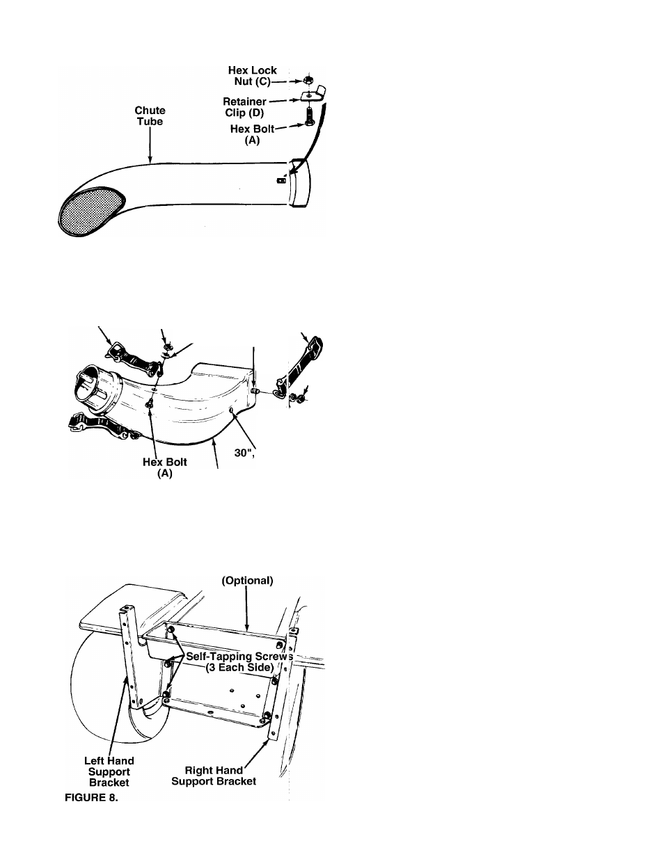
1.-Attach the retainer clips (D) to the bottom of the
----- lower tube as shown in figure 6. Secure with hex
bolts (A) and hex lock nuts (C).
2. Assemble two retainer straps (E) to the upper end
of the discharge chute as shown in figure 7.
Secure with hex bolts (A), spring washers (B) and
hex lock nuts (C).
FIGURE 6.
Retainer
Strap (E)
Hex
Lock
Nut (C) Spring
Washer (B)
Hole for
36" & 38" Decks
Retainer
Strai № (E)
Hex
Lock
Nut
(C)
Sp ring
Washer (B)
Hole for
32", 42" & 46"
Dec ts
Discharge
Chute
FIGURE 7.
Tool Tray
NOTE: When assembling the retainer strap to the
lower portion of the discharge chute, select the proper
-hole location for your deck as shown in figure 7.
3. Assemble retainer strap (E) to the lower portion of
the discharge chute, selecting proper hole as
shown in figure 7. Secure with hex bolt (A), spring
washer (B) and hex lock nut (C).
ASSEMBLY OF SUPPORT BRACKETS
(Group C)
NOTE: Units with twin cyiinder engines: Two
mounting brackets were included with your lawn trac
tor (part numbers 17077A and 17078A). Use those
brackets instead of the brackets supplied with the
grass catcher.
1. Attach the right and left hand support brackets to
the lawn tractor as follows,
a. Remove six self-tapping screws from the rear
of the lawn tractor. On some units, two of these
screws will hold either a tool tray or a fender
--------- panel. See figure 8.
Place the right and left hand grass catcher
support brackets in position as shown in figure
8. Secure support brackets (and tool tray or
fender panel if so equipped) to the tractor
frame with self-tapping screws removed in
step a.
If the grass collection system is removed for
any reason, it is not necessary to remove the support
brackets.
b.
NOTE: