Generac q-70g recreational vehicle generator, 1 generator control panel, 1 fuel primer – Generac Power Systems 0784-1 User Manual
Page 9: 2 start/stop switch, 3 fuse, Note, 2 optional remote start/stop panel, 2 j autoivlatic choke, 1 choke solenoid, Generator control panel
Attention! The text in this document has been recognized automatically. To view the original document, you can use the "Original mode".
Section 2 - Operation
Generac Q-70G Recreational Vehicle Generator
OPERATION
2.1
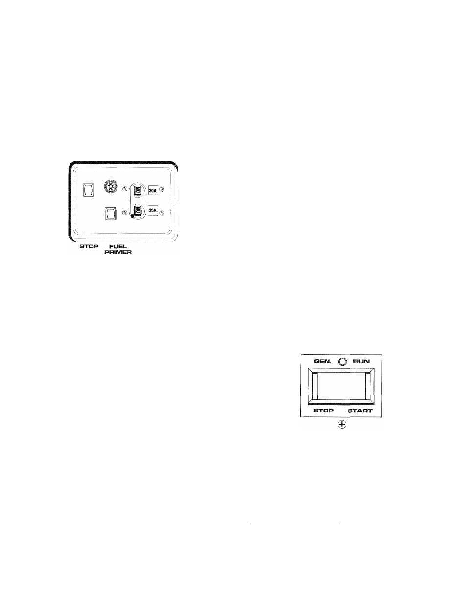
GENERATOR CONTROL PANEL
The following features are mounted on the generator
control panel (Figure 2.1):
Figure 2.1 - Generator Control Panel
IVIAIIM
START 15A BREAKER
♦ 2.1.1 FUEL PRIMER
Before starting a cold engine (if it has not been start
ed in more than two weeks), you must press this
switch for approximately five seconds to bring fuel
from the tank to the fuel pump. This rocker type
switch springs back into its original position when
you release it.
♦ 2.1.2 START/STOP SWITCH
To crank and start the engine, hold this switch in the
START position. Release the switch when the engine
starts. To stop an operating engine, press and hold
the switch in the STOP position until the engine shuts
off. The switch center position is the RUN position.
♦ 2.1.3 FUSE
The fuse protects the engine’s DC control circuit
against electrical overload. If the fuse element has
melted open due to overloading, the engine cannot be
cranked. If you must replace the fuse, use only an
identical replacement.
♦ 2.1.4 MAIN BREAKER
The main breaker protects the generator’s AC output
circuit against overload and provides a method of
turning OFF the generator’s 115/230-volt AC output
to the vehicle circuits. This generator has two 30-amp
circuit breakers.
NOTE:
If this generator has been reconnected for dual
voltage AC output (115/230 volts), you can install
line breakers having an amperage rating that is
different than that stated in Section 1.4 (Page 5).
The replacement line breakers consist of two sep
arate breakers with a connecting piece between
the breaker handles (so that both breakers will
operate at the same time).
2.2
OPTIONAL REMOTE
START/STOP PANEL
A remote mounted Start/Stop Panel (Figure 2.2) is
available that allows you to start and stop the gener
ator engine conveniently from inside the vehicle. The
model
9042
remote
panel
includes
a
Start/Stop
switch and a generator run lamp.
Figure 2.2
—
Optional Remote Panel
(Model 9042)
0
GENERAC
R.V.
GENERATOR
2 J
AUTOIVlATiC CHOKE
This engine is equipped with an automatic choke that
consists of two main components: a choke solenoid
and prechoke.
♦ 2.3.1 CHOKE SOLENOID________________________
During
engine
cranking
(Start/Stop
switch
at
START),
a
solid-state
choke
module
signals
the
choke solenoid to activate and cycle (choke on/choke
off) until the engine starts. The choke solenoid thus
opens and closes the carburetor choke valve only
when the engine is cranking. When the engine starts,
the choke stops cycling,
Generac®
Power Systems, Inc. "7