9 additional inforiviaiion, Additional information – Generac Power Systems 0784-1 User Manual
Page 12
Attention! The text in this document has been recognized automatically. To view the original document, you can use the "Original mode".
OPERATION
0tx
Section 2 - Operation
Cenerac Q-70G Recreational Vehicle Generator
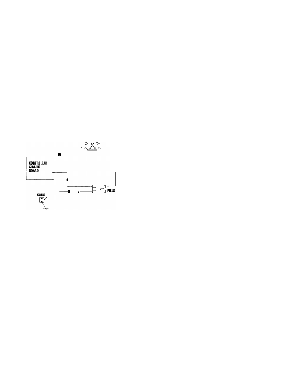
♦ 2.8.3 FIELD BOOST
The Controller Circuit Board houses a field boost
diode and resistor that are not part of the automatic
choke circuit. These two components are part of a
“field
boost”
circuit
(Figure
2.4).
During
engine
cranking only, a positive DC (battery) voltage is deliv
ered through the diode, resistor, brushes and slip
rings, and the generator rotor. Application of this
voltage to the rotor “flashes the field” whenever it is
started. Flashing of the field each time the generator
starts makes sure that a sufficiently strong magnetic
field is available to produce “pickup” voltage in the
stator windings.
Figure 2.4 - Field Boost Circuit
CLOSEST TO
BEARING
♦ 2.8.4 OVERVOLTAGE PROTEQION________________
A solid-state voltage regulator (Figure 2.5) controls
the generator's AC output voltage. This regulator sup
plies an excitation current to the rotor. By regulating
the rotor’s excitation current, the strength of its mag
netic field is regulated and, in turn, the voltage deliv
ered to connected electrical loads is controlled. When
the AC frequency is 50 Hertz, voltage is regulated at
115 volts.
Figure 2.5
-
Solid State Voltage Regulator
JÜV-
0
©
=
B
B
(S
©
^T^;'3-SE«SIMG
czzN-«(+)i TO ROTOR
(IIRECT CURRENT)
^tr,'T5hFR0M STATOR
------
~
EXCITATION WINDING
(ALTERNATING CURRENT)
The voltage regulator also incorporates a “voltage
surge protection circuit.” This circuit prevents trou
blesome surges in the generator AC output voltage.
Voltage surge is a common cause of damage to elec
tronic equipment.
2.9
ADDITIONAL INFORIVIAIION
• 2.9.1 25-HOUR BREAK-IN PERIOD_______________
The first 25 hours of operation is the break-in period
for the generator. Properly breaking in the generator
is essential to minimize fuel consumption and pro
vide maximum engine performance. During this 25-
hour break-in period, follow this procedure:
» Run the unit at varying electrical loads to help seat
the engine piston rings properly.
•
Check the engine oil level frequently. Add oil if
needed. It is normal for the generator engine to
consume more oil than is normal until the piston
rings have properly seated.
•
For the 75-hour operation following the break-in
period,
avoid
light
electrical
loads.
Load
the
generator at 50 percent (or more) of its rated
wattage capacity. Repeated light loads during these
75 hours can cause improper seating of engine pis
ton rings, resulting in blowby and high oil con
sumption.
• After operating the unit for 25 hours, complete the
tasks recommended under Section 2.10.2.
• 2.9.2 25-HOUR CHECK-UP______________________
After the 25-hour break-in period, contact a Generac
Authorized Service Dealer for the following mainte
nance. The vehicle owner is responsible for any
charges:
• Change the engine crankcase oil and oil filter.
• Inspect the cooling and ventilation openings.
• Check the engine ignition system.
• Inspect the entire electrical system.
• Inspect the engine exhaust system.
• 2.9.3 OPERATION IN HIGH GRASS
OR BRUSH
-A
WARNING
A~
Never operate the generator while the vehide
is parked over high grass, weeds, brush,
leaves or any other combustible substance.
Such materials can ignite and burn from the
heat of the exhaust system. The generator
exhaust system becomes extremely hot dur
ing operation and remains hot for a long time
after it has shut down.
1 O Generac* Power Systems, Inc.