D. chain tension – Poulan PRO 305 User Manual
Page 8
Attention! The text in this document has been recognized automatically. To view the original document, you can use the "Original mode".
•
Your saw is equ^ped with a Reduced-Kick
back Bar and a Low-^ckback Chain.
•
Always use the Reduced-Backback Guide
Bar and Low-Kickback Chain specified for
your chain saw model when replacing these
parts. See the “Specifications^ section.
e. ATTACHING THE BAR AND CHAIN
A
WARNING
Do not start the engine without the guide bar and
chain completely assembled. Otherwise, the
clutch can come off and serious injury can result.
I CAUnON: I Wear protective gloves when han
dling or operating your saw. The chain is sharp
and can cut you even when it is not moving!
1. Removetheharclampnuts, bar clamp, and ]}}astic
spacer if you have not already done so. Discaard
plastic spacer.
2. Turn the adjusting screw (Fig^ lO) counter
clockwise to move the adjusting pin almost as far as
it will go to the rear.
3. Mount the guide bar imth the slotted end over the
moimting studs. Figi^ 8 . Position the adjusting
pin in the adjusting pin hole. Figure 8.
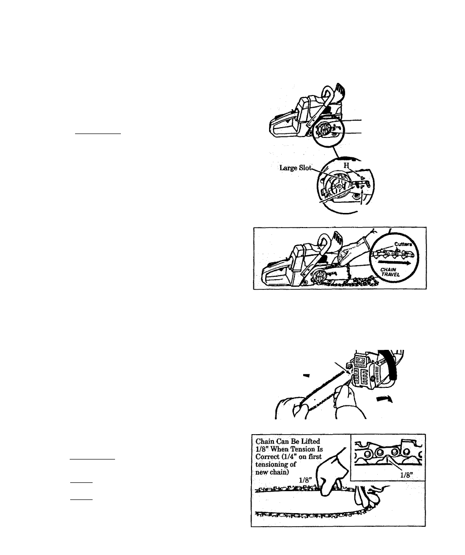
4. Hold the chain with the cutters facing as shown in
Figure 9 (inset).
5. Place the chain over and behind the clutch drum
and onto the sprocket. Figure 9 . Fit the bottom of
the drive links between the teeth in the sprocket.
6. Slide the ^de bar towaid the rear of the saw as far
as possible.
7. Start at the top of the bar and fit chain drive links
into the groove around the guide bar. Figure 9.
8. Turn the adjusting pin clockwise until the chain is
snug in the guide bar groove. Figure 10.
D. CHAIN TENSION
• Ck>rrect Chaiu Tensipu is very im^rtant—
- A loose chain will wear thè bar and itself
- A loose chain can jtunp off the bar while you are
cutting
- A tight chain can break or damage the saw and/
orbar.
•
The chain stretches during use, especi^y
when new. Check tension periodically as follows:
- each time the saw is used;
- more frequently when the chain is nev^
- as the chain warms up to normal operating
temperature.
• Chain tension is correct when the chain:
~ can be lifted about 1/8" from the Guide Bar at a
point near the middle of the bar and
will move freely around the bar.
installing a new chain, allowthe chain to
be lifted 1/4" from the bar. Thereafter, follow the
instructions as indicated.
• Chain tensioning procedure:
I WARNING: i Always wear ^oves when handl-
ihg the chain. The chain is shaxm and can cut
you even when it is not moving!
NOTE; The bar clamp nuts must be no more than
finger tight to tension the chain correctly.
NÓTE; Hold tip of guide bar up through step 4.
1. yft up the tip of the guide bar and turn the adjust
ing screw clockwise until the chain does not sag be
neath the guide bar. Figúrelo.
2. Check the tension by lifting the chain from the
guide bar at the center of the bar. Figure 11.
9. Hold the guide bar against the saw frame and in
stall the bar clamp,
10, Replace the bar clamp nuts and tighten finger tight
only. Tighten bar clamp nuts after chain is
tensioned.
IL Proceed to the “Chain Tension” section.
ole Above Slot
Bar
Mounting
Studs
Adjusting Pin Hole
Figures
Figure 9
3. Cohtmue adjusting the adjusting Screw until the
tension is correct.
4. Lift up the tip of the guide bar and tighten the bar
clamp nuts with the scrench.
6. Rechecfc chain tension. Figure 11.
Turn To
Increase
Chain
Tension
Adjusting Screw
Turn To
Decrease
Chain
Tension
Figure 10
Figure 11
-8-